A few years ago, I set out to reinvent photography. I didn’t have a good idea how to do this, I just knew I wanted to make something original, and combining photography with my electronics skills seemed like a good way to do that. It failed at reinventing photography, but I succeeded in writing a clickbait first sentence, and the process was lots of fun too.
It all started one night, when I was having drinks with a friend and looking for something new to do with photography. Our conversation went something like this:
- I need to do something original with photography.
- Mmhmm.
- Maybe I could combine technology and photography to create something new, but what could it be?
- Hmm.
- I know! I’ll make a light stick thing.
- Mmm.
The idea was great, I would use a LED strip to display images in mid-air, like those persistence of vision displays. I could set the camera to record a long exposure, then move the strip and trace a pattern in the air. I had never seen anyone do this before, so the first thing I did was what everyone does when they have a groundbreaking idea: I searched the web to see if this already existed.
The second thing I did was what every self-respecting inventor does when they have a groundbreaking idea: I looked at the first two search results, saw that none of them resembled what I had in mind, said “Well, this conclusively proves that nothing like this has ever been done!” and started working on it.
I call it… Ledonardo!
High-level idea
The basic idea is a device that will be a long strip of individually-addressable LEDs, which means that each LED on the strip can show a different color. I would also create a microcontroller with some software that allowed it to change the LEDs’ colors in such a way that they could show photos and patterns in the air. Since a long bar is almost one-dimensional, to show photos and patterns you’d have to move the bar along the path you want the image to show, while the camera’s shutter remains open. This means you can pretty much only use this for night photography or light painting, but the result would be fairly impressive.
Because it’s hard to explain, especially to people with no experience in long-exposure photography, here’s a video of how taking a photo with the final version of the bar (spoiler alert) works:
Basically, you keep the camera shutter open for many seconds, move a light source in front of the camera, and (if you’ve done everything right) the trajectory of the light source shows up on the photo.
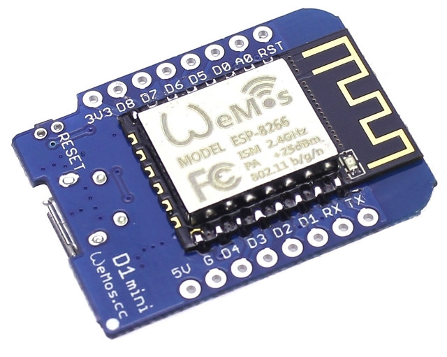
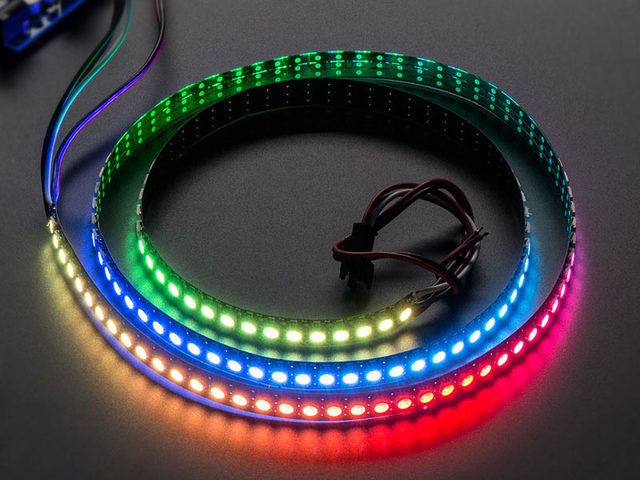
I already had some WS2812 LED strips and I decided to use the ESP8266, my go-to microcontroller. The ESP8266’s built-in WiFi is extremely handy for cases where you have complex interfaces, since you can use a mobile phone to control it. That way, I could upload photos from the phone to display on the strip.
Please excuse the draft quality of the photos in the rest of the article, they are quick tests I made while making the bar.
Hardware details
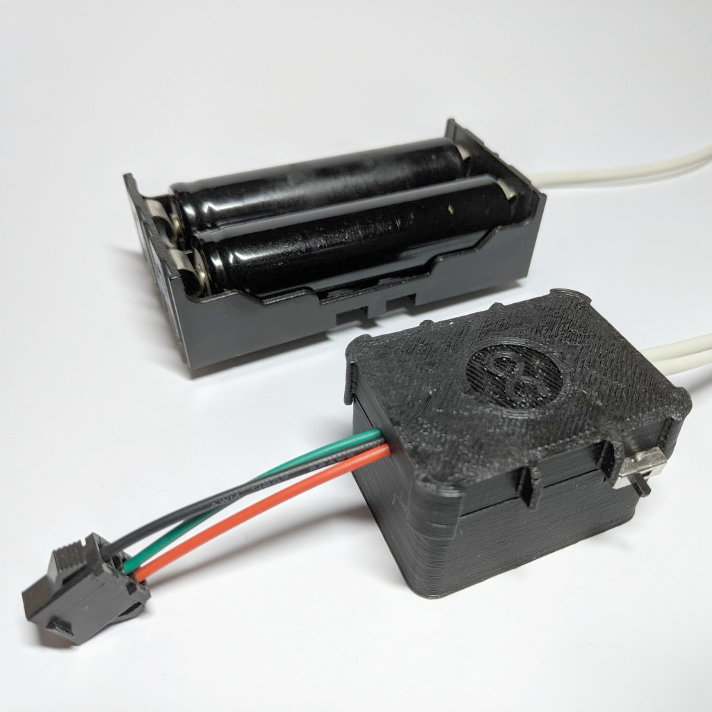
The hardware didn’t really change at all from the first iteration. I’m using a WeMos D1 mini as the ESP8266 board, with its 5V pin connected to two 18650 3.7V batteries in series, which usually provides power for around two hours of shooting, depending on LED intensity. The LEDs are also connected to the batteries and the output pin of the WeMos, and that’s pretty much it for the schematic. I also added a small switch so I can cut power to the whole assembly when I’m not using it.
The other hardware-related aspect of this is a small box I designed and 3D printed to house the microcontrollers. I did this because otherwise the microcontroller would dangle from the wires and they’d frequently get cut. With the box, everything fits neatly inside, all the wires are held by the edges of the box so the stress concentrates on the plastic case and wire shielding, and there is no tension on the solder joints.
First attempt, network-based, sparse strip, square pixels
I ran some back-of-the-envelope calculations with the image dimensions, bits per pixel, etc and realized that the 2 MB storage of the ESP8266 would only be enough to fit one or two images. I would also need to recompile and deploy the firmware every time I changed something, which I didn’t want to do. Instead, I decided to send the image over the WiFi connection and simply display it on the strip. This had the added advantage that the computer handled the complicated parts, i.e. resizing the image, timing it according to the speed you walked, etc. All the microcontroller had to do was display each column as it received it.
Another consideration to pay attention to was image dimensions. Since the strip only had 50 LEDs (30 per meter), a square image would be resized to 50x50 pixels, which was pretty small but hopefully usable. LED strips with double the LED density exist, and I ordered one, but it would take a month before it arrived so I would have to make do with the sparse one for now.
You can see the results of this initial version in the images below:
Second attempt, network-based, dense strip, non-square pixels
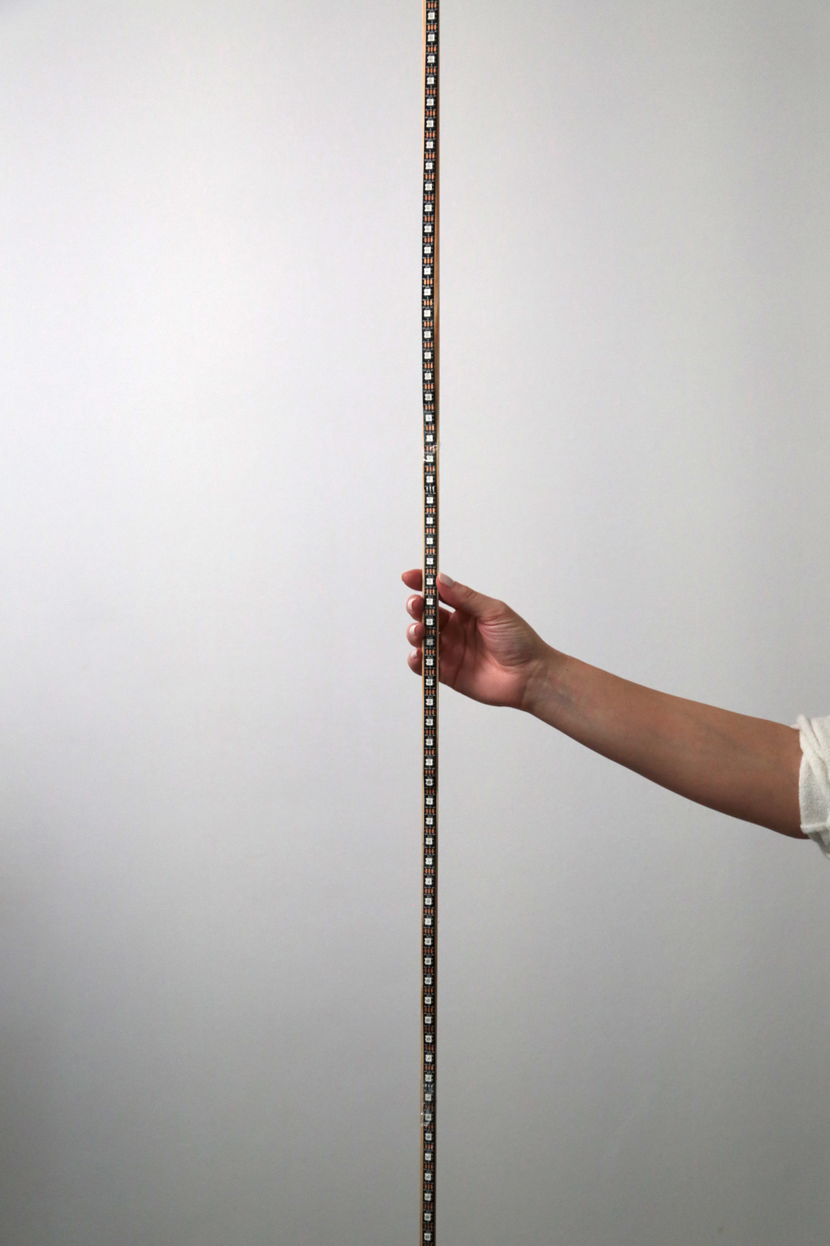
My new strip finally arrived, with twice the number of LEDs per meter! This meant a higher vertical resolution, which means sharper images!
While testing with higher-resolution images, I realized that, even though I only had 100 vertical pixels to play with, that didn’t mean I had to constrain myself to 100 horizontal pixels as well! Since the horizontal resolution was only governed by colors changing at various times instead of how far apart LEDs were spaced, I could theoretically get infinite horizontal resolution. Practically, I’m still limited by how fast the LEDs can change colors, but that’s the only limitation. If my LEDs can change colors every 10 ms, I can get 100 pixels per second, which is around a pixel per cm at walking speed.
Unfortunately, going over the network was problematic, as I only managed to get 5 pixel changes per second in my tests. That was much better than before, but still not great.
More testing
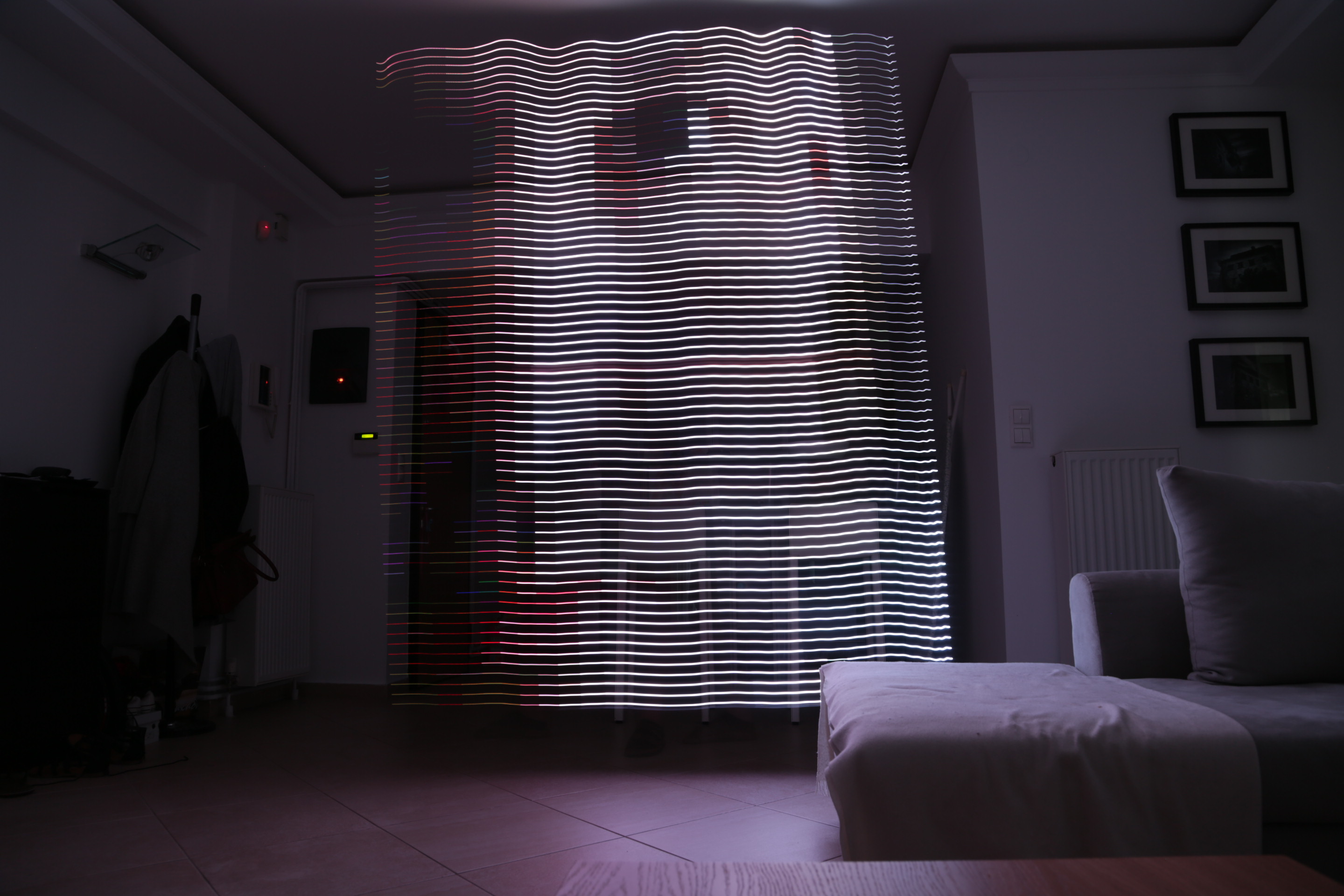
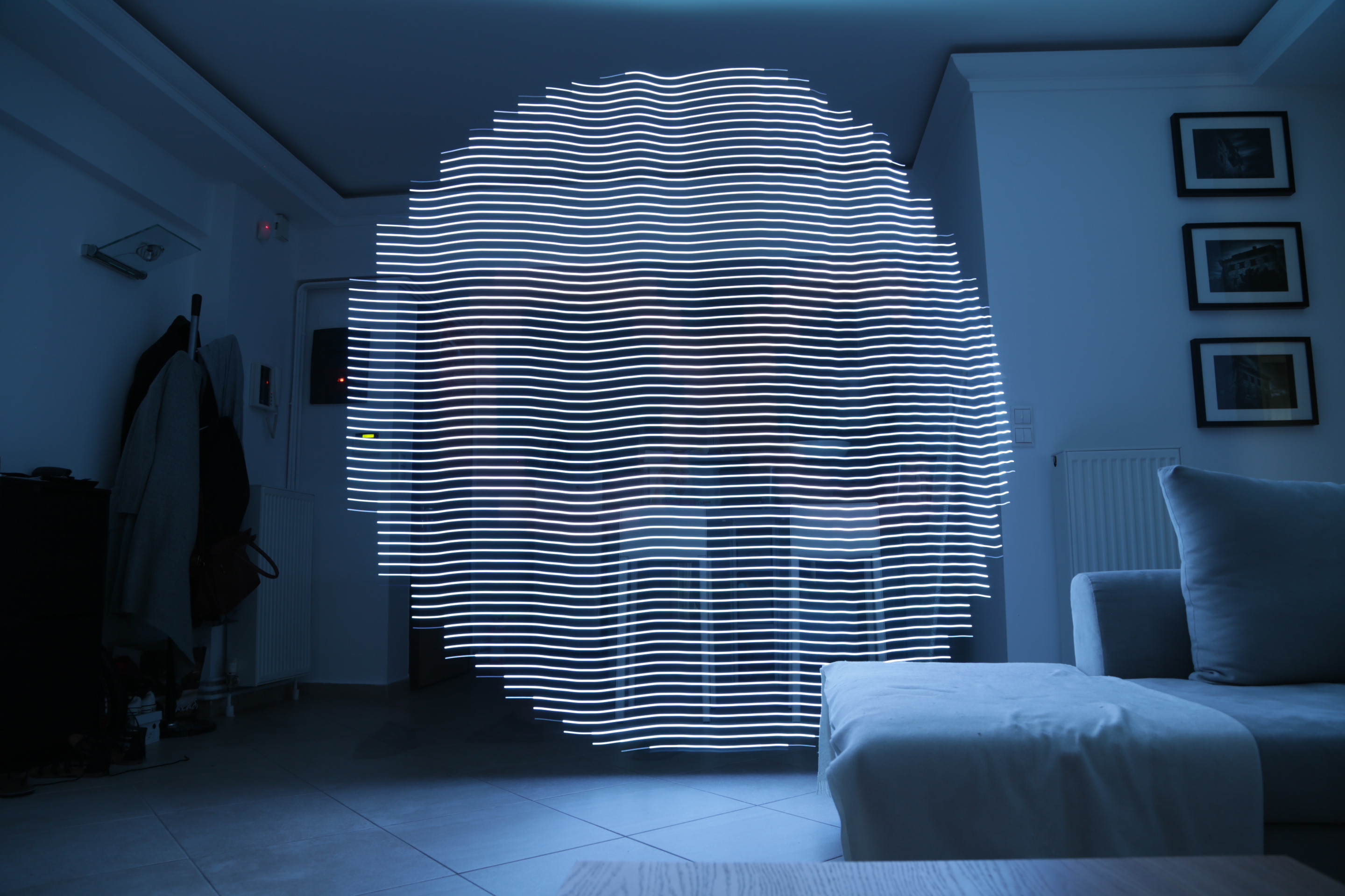
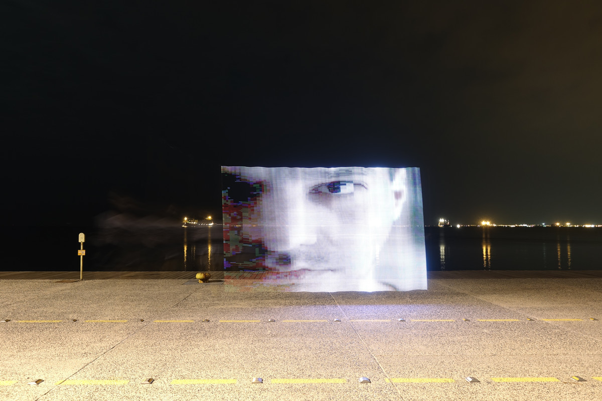
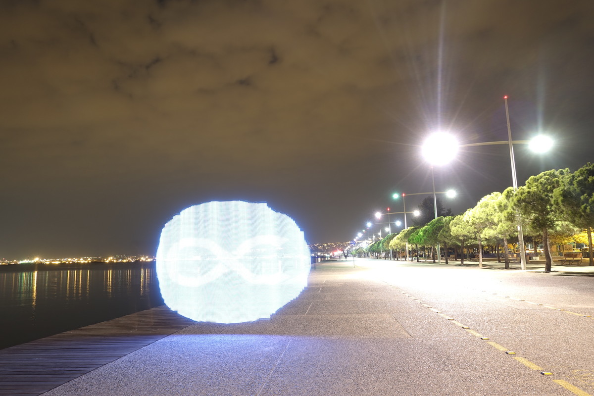
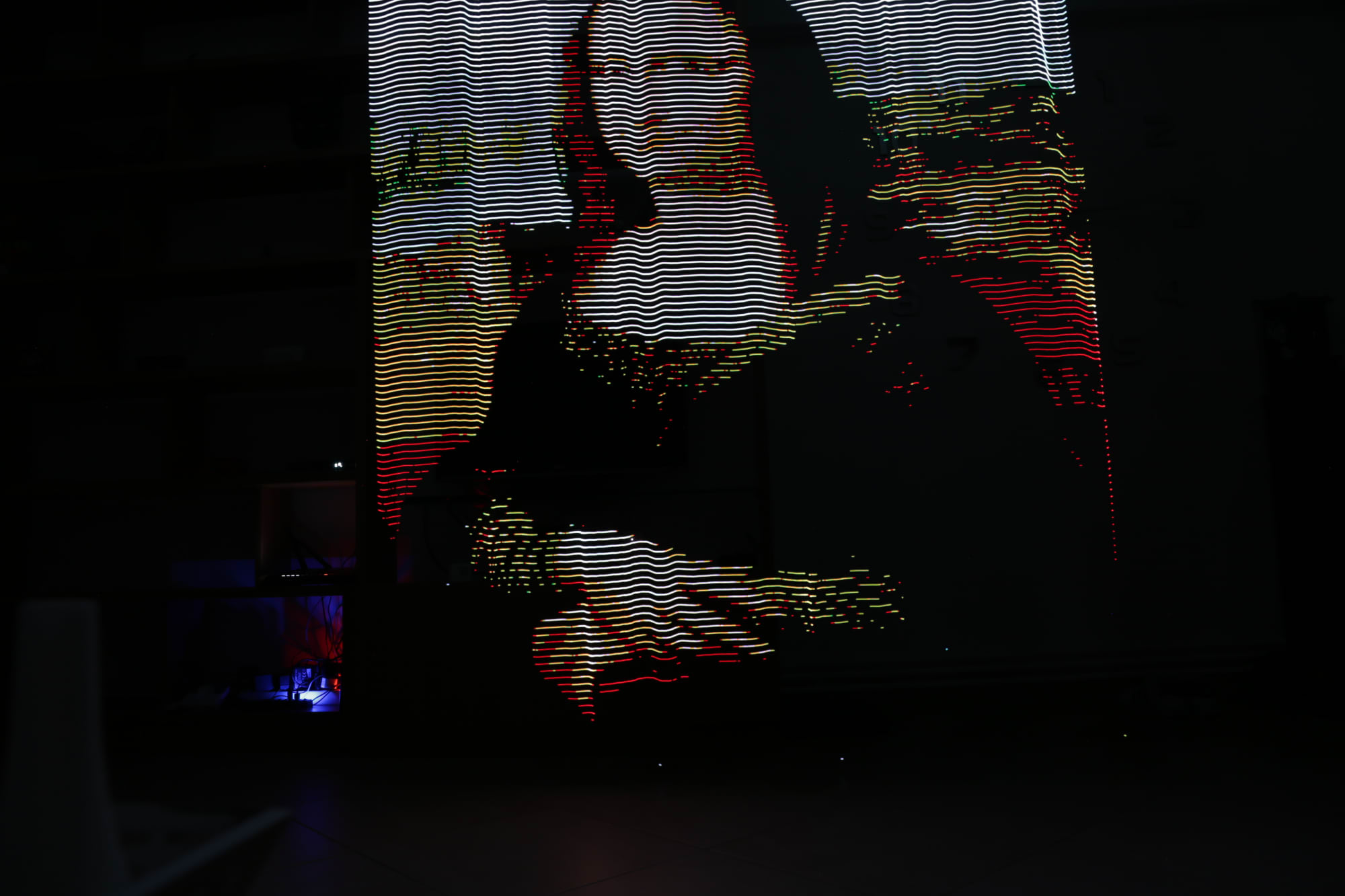
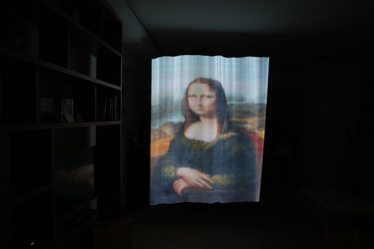
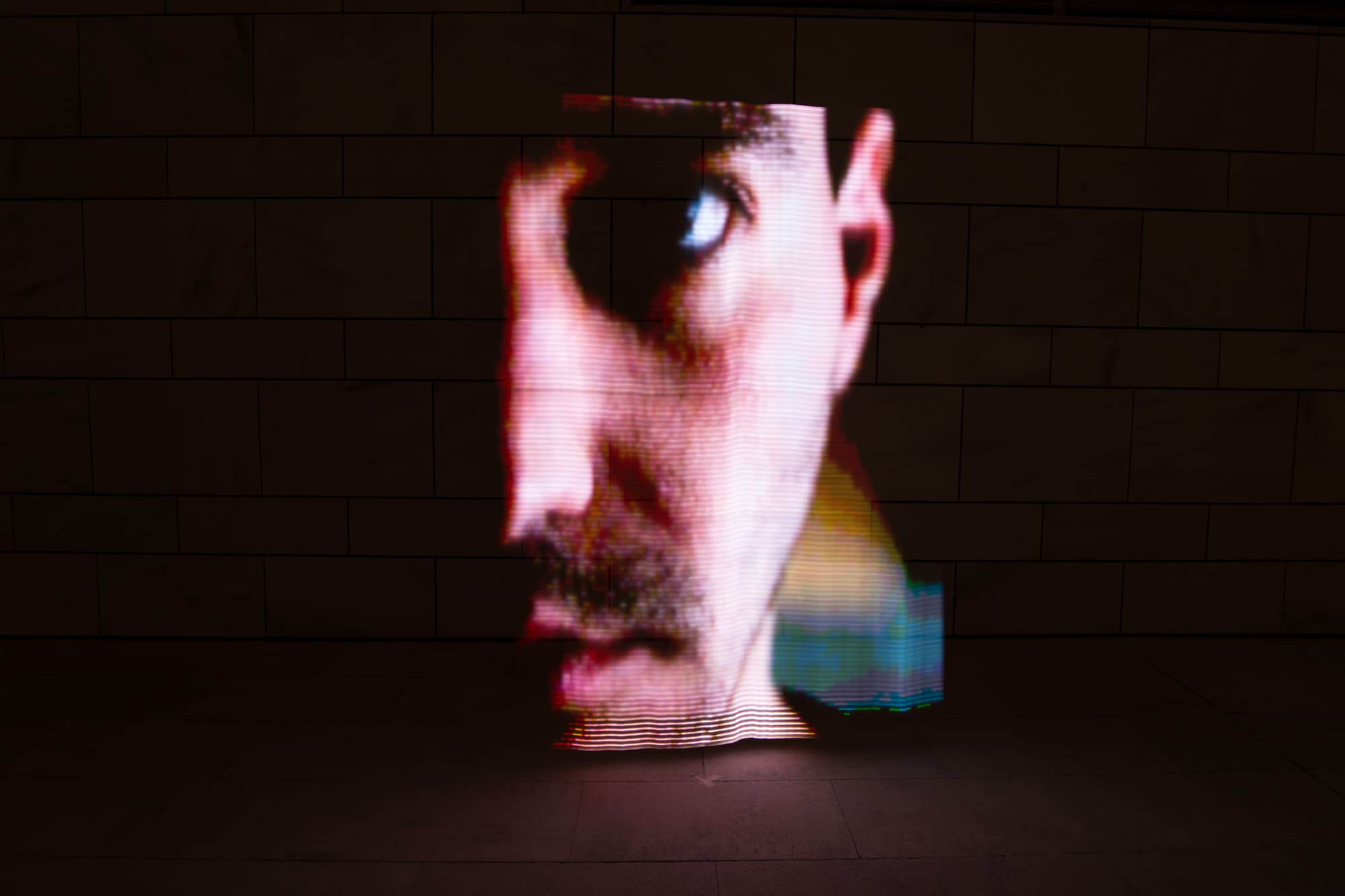
Another problem with going over the network is that sometimes you get dropped packets. This means that, when the computer sends the column, it is lost in transmission for whatever reason, and the microcontroller never receives it, so it can’t display it. If you look closely at the images, you can see that sometimes a column will not have arrived, which leads the firmware to just repeat the previous column. This creates jagged edges and repeated columns in detailed images.
The images below illustrate this, where the white in the eye of the portrait is square and the circular logo has lots of jagged edges.
Python rewrite, SD card, color problem
Due to the network issues detailed above, I decided to rewrite the whole thing using an SD card. I also wanted to write a converter program to take any image type (JPEG, PNG, etc) and convert it to a bitmap that could be easily and quickly read from the card and displayed. This would improve display, because there would be no more dropped packets. It would also greatly increase horizontal resolution, as reading from the SD card is much faster than going over the network, so you get more color changes per second.
I decided to write the microcontroller firmware in microPython this time, because I had really started to hate C. The tooling that resized the images and generated the bitmaps on the computer side was also written in Python.
I got a simple SD card shield for the WeMos, which microPython made trivial to use (you basically just read the file system as normal).
It only took a day to rewrite everything, as much of the code of the image-sending program was already in Python.
Unfortunately, and much to my dismay, reading the pixels and writing them one by one to the LEDs was taking so long that I could only display 8 columns per second.
I spent quite some time trying to optimize this, but there’s only so much optimization you can do to a two-line for loop.
Jumping into the micropython source for the LED library implementation, I realized I didn’t even have to keep the for loop!
I could just directly assign the data I read from the SD card to the internal buffer of the LED library instance and display it.
This sped my code up tenfold, and now I could cram much more detail in a centimeter of display!
However, I now had a different problem! The colors were off, as you can see in the images below.
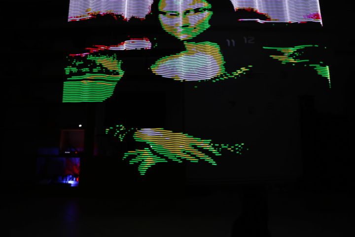
Color problem fixed
Apparently, someone decided to make the WS2818 LED addressing order “green, red, blue” instead of “red, green, blue” that is the standard. That took a bit of debugging, but I eventually found the problem and quickly fixed it. Now all the colors showed up as they should!
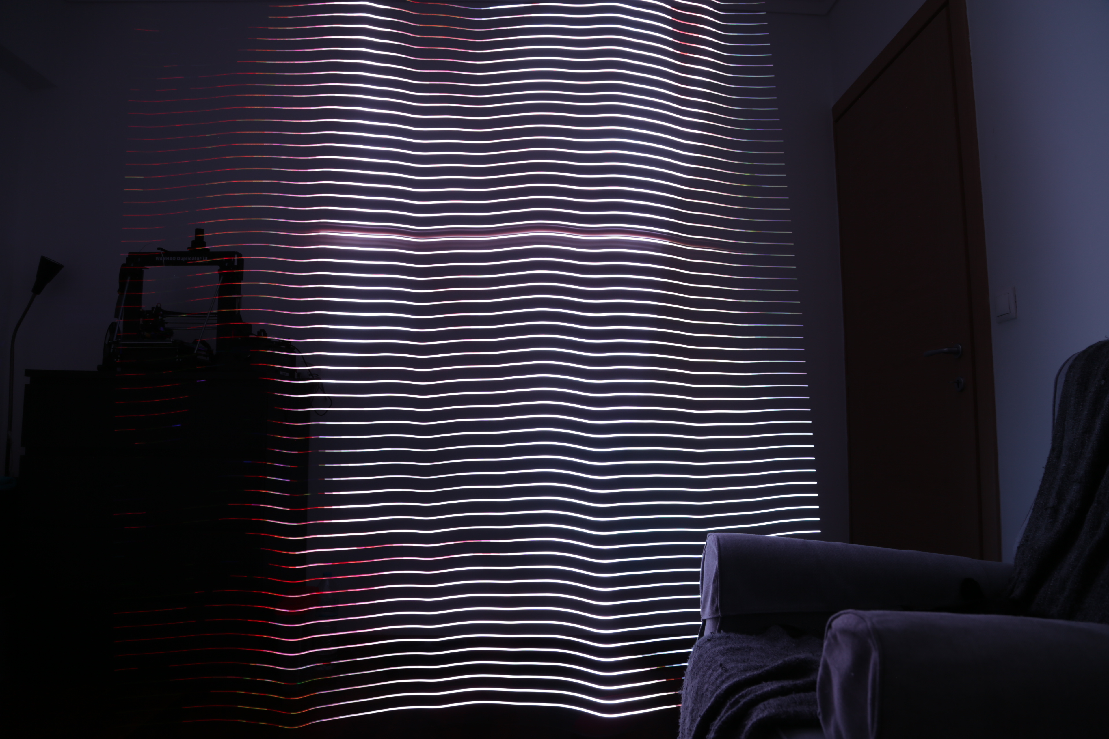
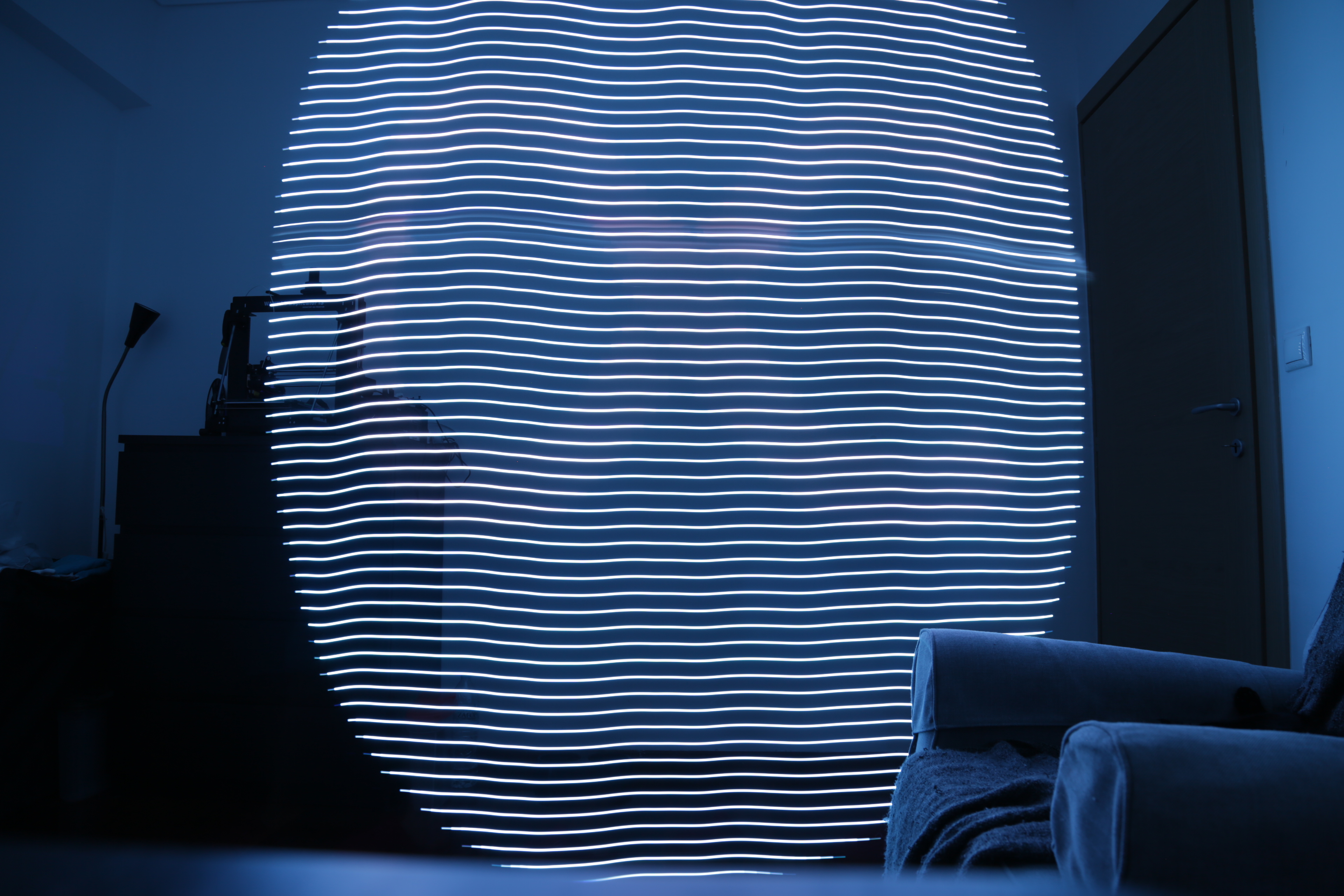
I still didn’t like the striped LED lines that appeared because the LEDs were basically points of light, I wanted the final result to look a lot more “solid”. However, I did figure out that the LEDs were way too bright for the camera’s settings, which caused the images to appear washed out. I turned the brightness down to 1% of the total brightness, which made the images look much nicer!
Diffuser, gamma correction!
I began thinking about how I could create a light diffuser, to get the images looking much more even and less like a zebra. To do that, I would need to use some sort of semi-opaque and color-neutral material, such as paper or, even better, tracing paper. However, I also needed to put some space between the diffuser and the LED, to allow the light some space to actually diffuse.
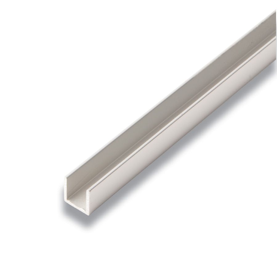
I considered designing and 3D-printing spacers that would clip onto the wooden bar and wrapping pieces of paper around them, but that was a bit too difficult to make and damage-prone. I visited my local hardware store and discovered plastic U-channels for running wires through. These are basically a long, square plastic pipe with one side exposed, which was perfect for me.
I pulled on the sides of the channel a bit to open up, so I could get a wider angle instead of 90 degrees, which would in turn give me a wider bar. This worked pretty well, although the whole thing looks like the hacked-together home prototype it is.
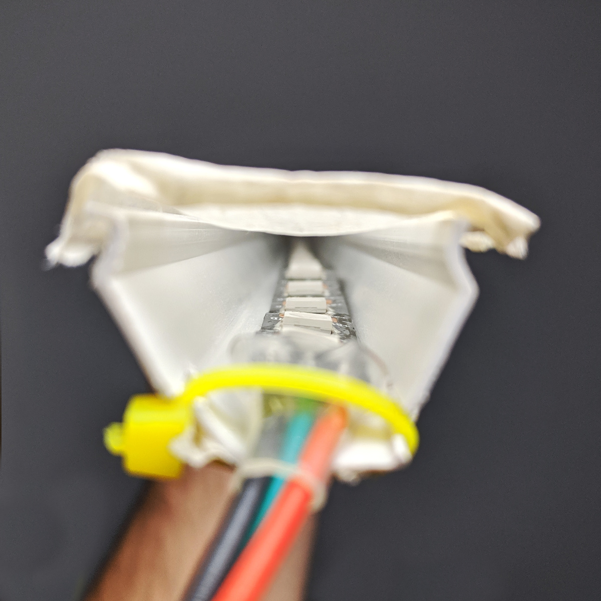
I glued the LED strip along the bottom side of the U-channel, soldered the wires that ran to the microcontroller on the exposed end and connected everything up. I then ran some masking tape over the open end of the channel and stuck it to its two sides.
I also came across a vital piece of information somewhere, completely at random: LEDs don’t have a linear response! To represent a color as our eyes see it, you can’t just set the RGB led to those color’s values, you first need to perform what is called Gamma correction so that the colors will show up correctly. Fortunately, this was very easy to do in the converter program, so I quickly implemented that as well.
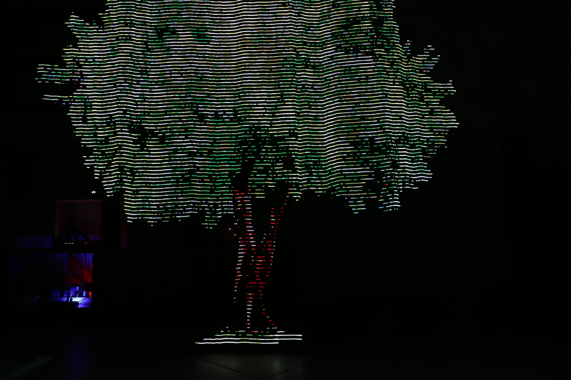
I tried some test photos, and the results looked amazing. You still need a steady hand, but the LEDs themselves work great.
Done
At this point, I consider the project done. It’s good enough to use, very sturdy, and works great, but one thing surprised me negatively. I thought that it would be fantastic to be able to display photorealistic images in mid-air, but it turned out that abstract patterns and colors make for far more interesting photographs. If I knew this from the start, I might not have spent so much time obsessing about the horizontal resolution, since it doesn’t really matter.
Another thing I learnt long after I started working on this is that someone else had, indeed, made this. They called theirs the pixel stick, whereas I don’t even know what to call mine yet. I think they beat me to it only slightly, but it doesn’t really matter, since I did this for fun and I had a lot of that.
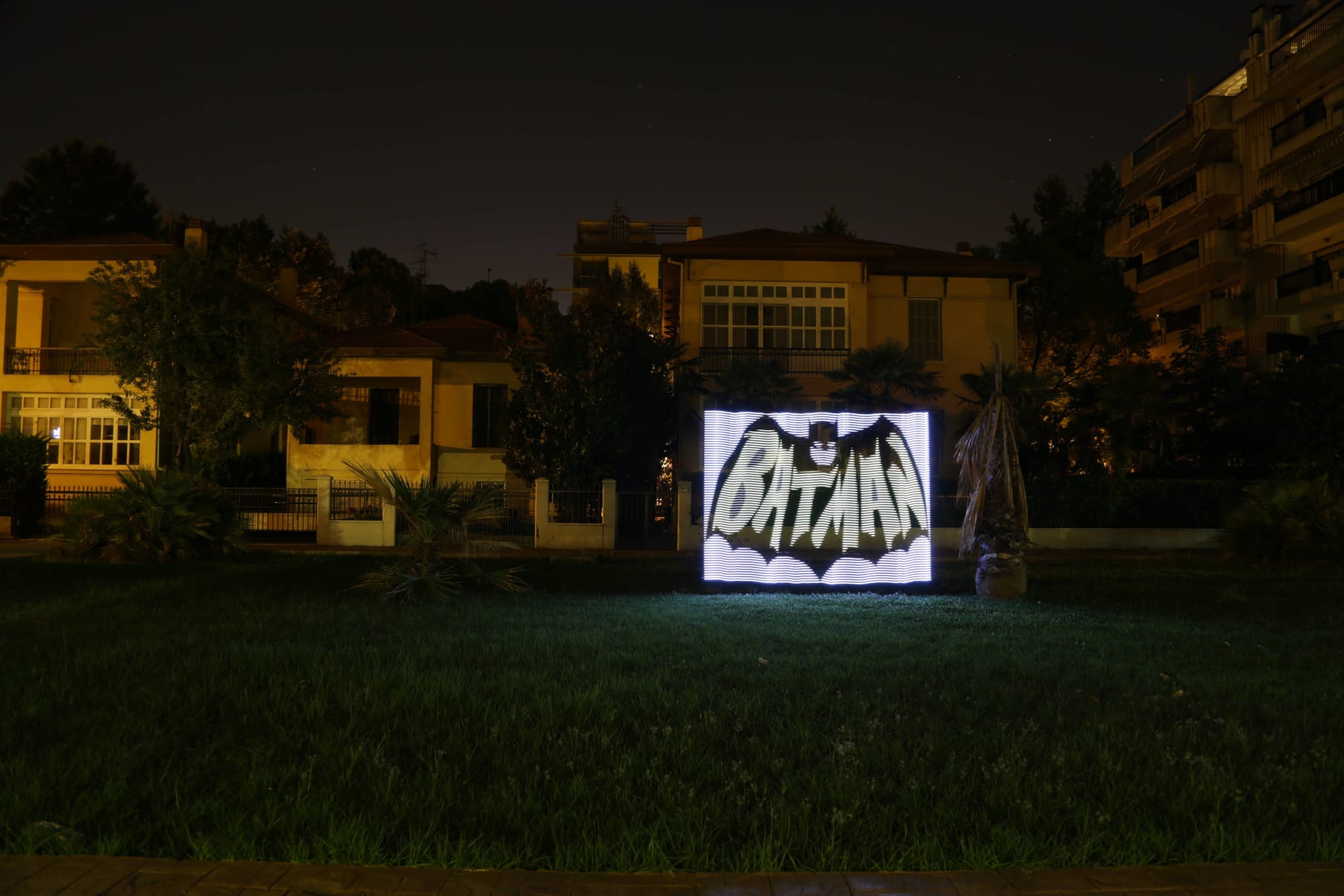
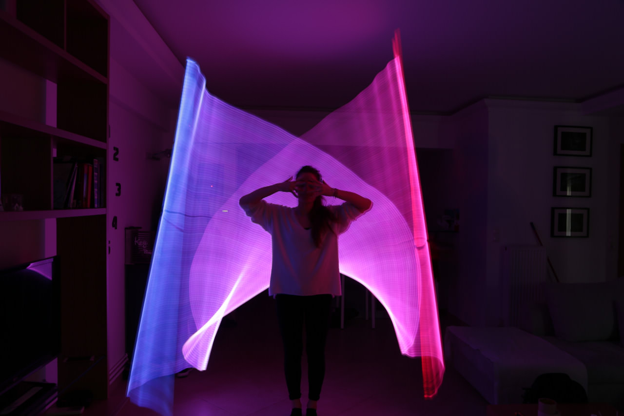
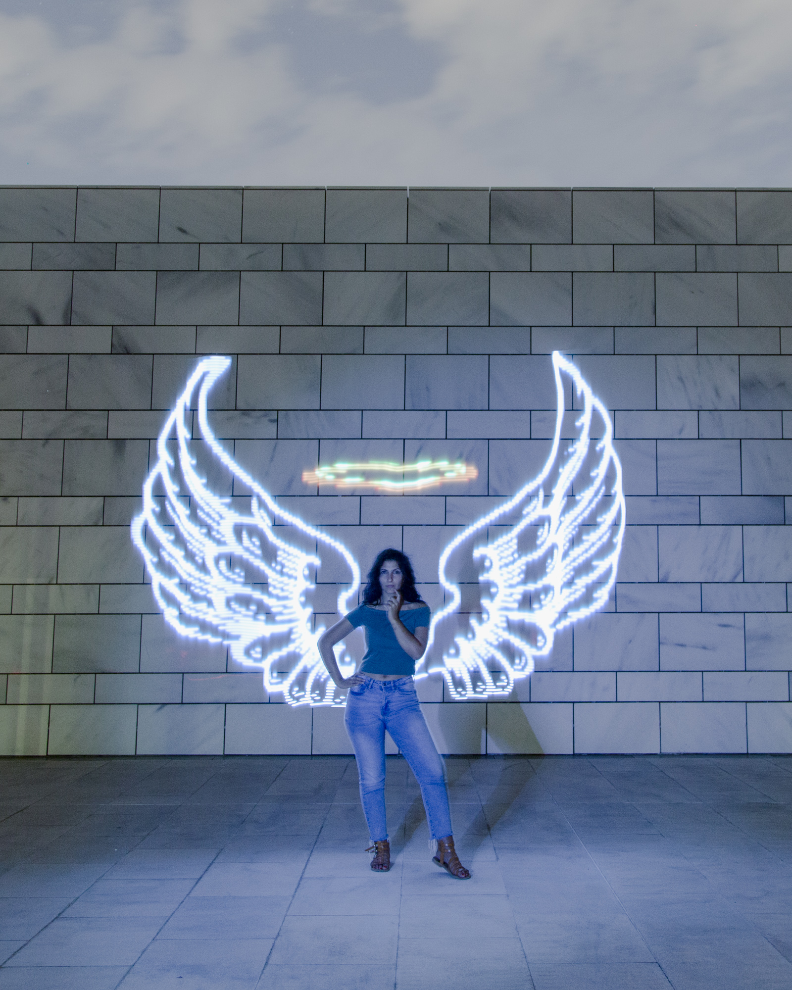
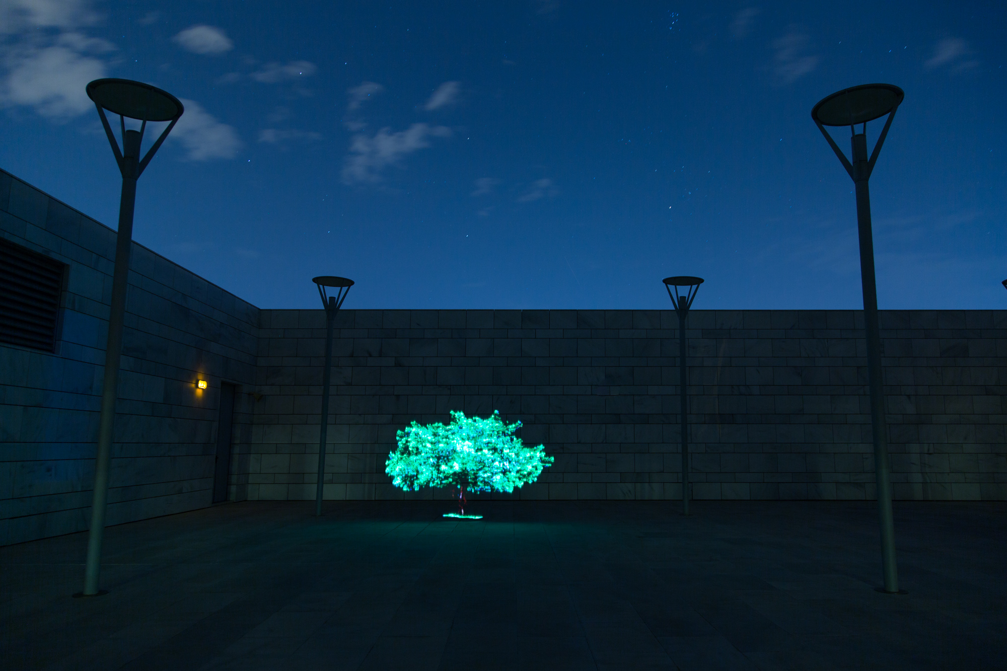
As a parting gift, here are some more “production” images that I shot with Ledonardo:
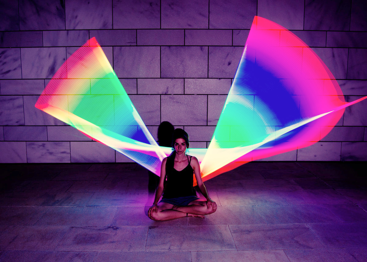
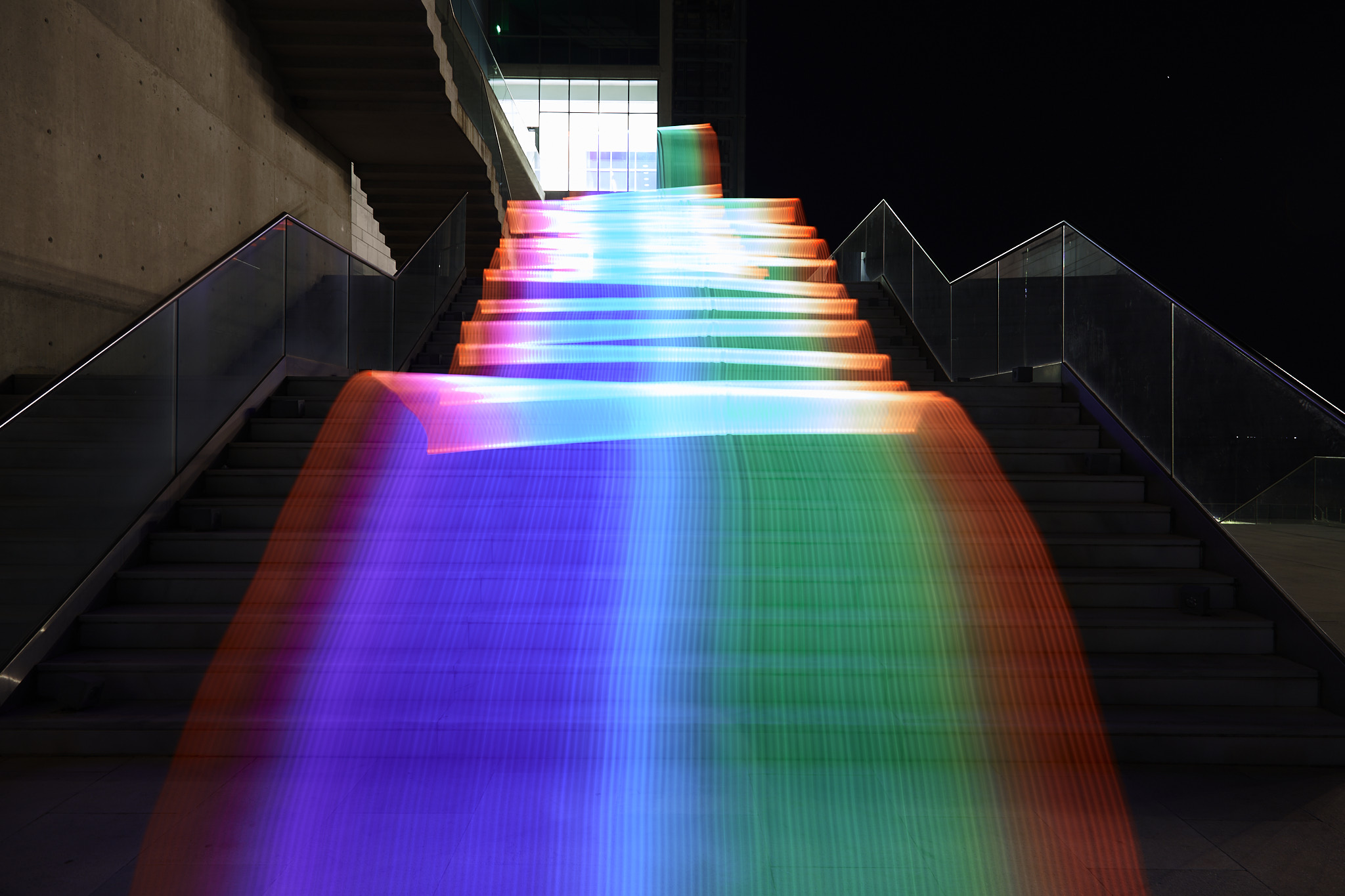
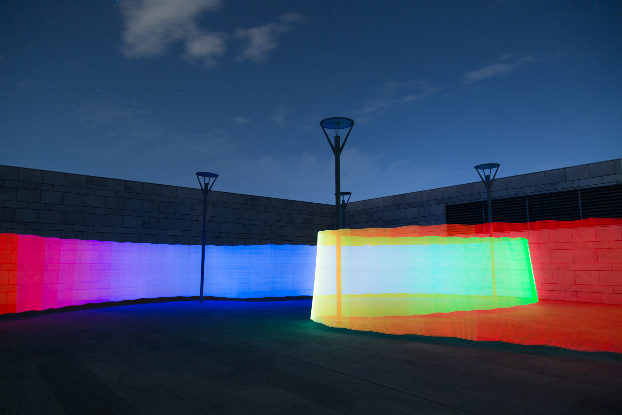
That’s all for this project, I hope you enjoyed reading about it as much as I enjoyed making it! I’ve uploaded the code to a git repo, so if you want to take a look at it just visit the ledonardo repository.
If you want to see more of my photography-related escapades, I post my photos on Instagram under the handle stavroskorok and my maker-related things on IG at stavrosware. You can also follow me on Twitter or Mastodon.
I’d also like to thank Maria, Alexandra and Anna for their help and support.
If you have any feedback or questions, please leave a comment below!