I recently received my shipment of the ESP8266 and NodeMCUs I had ordered, and I started playing with them. My overall experience is coming soon in another post, but the verdict so far is that it’s fantastic and I love it for ever.
Since the ESP8266 is pretty much a $2, postage-stamp sized powerhouse, it’s usable in a wide variety of projects. I’ve been intrigued by the Amazon dash button ever since I saw it, and I wanted a hackable button like that for my own projects. So, I set out to make one!
Introduction
 A preliminary schematic.
Before I begin, I have to say I’m a complete newbie at this, having only dabbled in hardware for a few days in total, so everything you read here is probably horribly wrong. If that’s the case, please leave a comment below, I’d appreciate the improvement. However, for now I’ll just do what everyone else does and pretend to be an expert, and continue.
From the first time I saw the Amazon dash button, I was impressed by its simplicity, and thought that it, or something like it at around the same price point, would be very useful. Unfortunately, it’s not open at all, and the more open alternatives are still not very open and cost at least seven times as much. Therefore, the reasonable thing for me to do is to sink a few thousand dollars’ worth of my time into making one myself!
Since I’m too lazy to cook, I thought that it would be great if I could create a button that would order food for me. Here in Greece, there are websites that aggregate all the shops that deliver food and allow you to order from the web, which is perfect for integrating into a button. So, I decided that what I wanted is a button that I could press and have food arrive a few minutes later!
The first step in building any hardware project is, of course… the prototype!
The prototype
To whet your appetite, let’s start with the complete prototype:
In case you didn’t catch that, you press a button and get food. Like a lab rat. Wirelessly. We are truly living in the future.
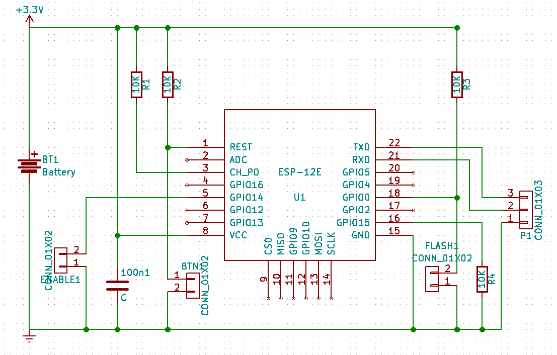 The KiCad schematic.
The first thing I like to do when starting a hardware project is to draw the schematic. To do this, I use the excellent KiCad, which I started using all of two days ago, and has been great ever since.
This schematic might look more complicated than it really is. There are four resistors in all, which are pretty much just required pullups/pulldowns for the ESP to boot (rather than get flashed), there are a few connectors for the FTDI programmer, the button itself, a button to put the ESP in flashing mode, a decoupling capacitor and a button to disable ordering (in certain circumstances, which we’ll see more about later on).
I’m not really sure why the ESP needs these resistors in order to boot. I would think that a better design would be to boot by default, and require the GPIOs to be pulled in order to get in the other modes, but I’m sure that the folks at Espressif know a bit more than me.
The general design of the emergency food button (hereafter EFB for short) is this: Everything is only there so the ESP can boot, except that there’s an additional button (hereafter referred to as “the button”) that momentarily connects the reset GPIO to the ground when pressed, and resets the ESP.
Implementing the prototype
After drawing the schematic, which is what should work in theory, it’s time to bust out the breadboard and start connecting the wires. After a lot of wires, the prototype will hopefully look very impressive, which is what we want.
Once you’re sure everything is connected properly, it’s time to power it all up. Connect the power source, and watch carefully. If you don’t see any smoke, it probably means nothing broke, and it’s time to go to phase two!: The programming phase.
The programming phase
To someone such as myself, a software developer (who still doesn’t know any C), that’s the easy part! Luckily, the amazing Arduino firmware for the ESP means that we can use the ever-familiar Wiring language with all the ESP goodness such as WiFi.
As mentioned earlier, the only thing the ESP will do is reset when the button is pressed. So, what the program needs to do when woken up is connect to a WiFi network and issue an HTTP POST to an endpoint of our choice. In this case, our choice is a Gweet channel, where a Python script listens for the POST and will place the actual order.
Here’s some simple code to do just that:
#define LED 2
#define FAILSAFE 14

void send() {
    HTTPClient http;
    http.begin("https://queue.stavros.io/things/");
    http.addHeader("Content-Type", "application/x-www-form-urlencoded");
    http.POST("command=food&store=noodle+bar");
    http.end();
}


void setup() {
    pinMode(LED, OUTPUT);
    pinMode(FAILSAFE, INPUT_PULLUP);
    digitalWrite(LED, LOW);
    WiFi.mode(WIFI_STA);
    WiFi.begin("mywifi", "mypass");
    if (WiFi.waitForConnectResult() != WL_CONNECTED) {
        ESP.deepSleep(0);
    }

    if (digitalRead(FAILSAFE) == LOW)
        send();
    digitalWrite(LED, HIGH);
    ESP.deepSleep(0);
}

void loop() {}
There’s actually a little bit more code there that’s not shown, but it’s just a few lines to enable the ESP to be flashed with updates over WiFi. The only change to the behaviour for this is that the EFB waits for thirty seconds after waking up for any potential flashing attempts before sleeping.
The astute reader will notice (I always try extra hard to notice things when I read that sentence somewhere, so consider yourself outed) that this design means that the EFB will ALWAYS order food when it wakes up, regardless of whether we pressed the button or not (for example, when we change the battery). That potentially fattening downside is why the “enable” switch exists. Short that jumper, and the ESP will order food when booting, leave it open and it will never order anything.
There are some other ways one might implement this. For example, one might use a capacitor to keep a GPIO high for a few seconds after the button is pressed and then read the value in the code, but I think that one just overengineers things where simpler solutions are just fine, and one should stop doing that.
The next level
Of course, the eagle-eyed reader may notice that the breadboard above is slightly larger than the button, and that we might have some difficulty fitting the former into the latter. Thus, we must do something nobody has done before: Design and manufacture a PCB!1
To do this, there are many options: Eagle, Altium, and other, even more expensive options. What I used, have heard good things about and liked immensely, however, is the fantastic and open source KiCad, as I said earlier. I haven’t tried any of the others a lot, but I found KiCad’s manual wiring helpers are very convenient. I started off using the autorouter, but doing the wiring by hand is pretty easy and fun.
The most important thing when designing the PCB is, apparently, getting the fabrication parameters right. I used DirtyPCBs for fabrication, and their parameter page is a bit convoluted for someone who doesn’t know what the terms mean. I hope the boards end up fine.
The KiCad parameters I used for DirtyPCBs, in case you care, are:
- Min track width/min clearance: 0.127mm (0.2 to be safe)
- Min via diameter: 0.7112mm (0.8mm to be safe)
- Min drill diameter: 0.2048mm (0.4mm to be safe)
When exporting, check “use protel filename extensions” to make your life easier.
Routing the PCB
Connecting all the components to each other properly is the main and fun part. It’s rather easy, even for a complete novice, as KiCad does most of the work for you and usually doesn’t even let you make a mistake. It will take care to put all the wires at a good distance from each other, to make sure connections don’t overlap, and that you’ve connected all the components that need to be connected and not connected any of the components that don’t need to be connected.
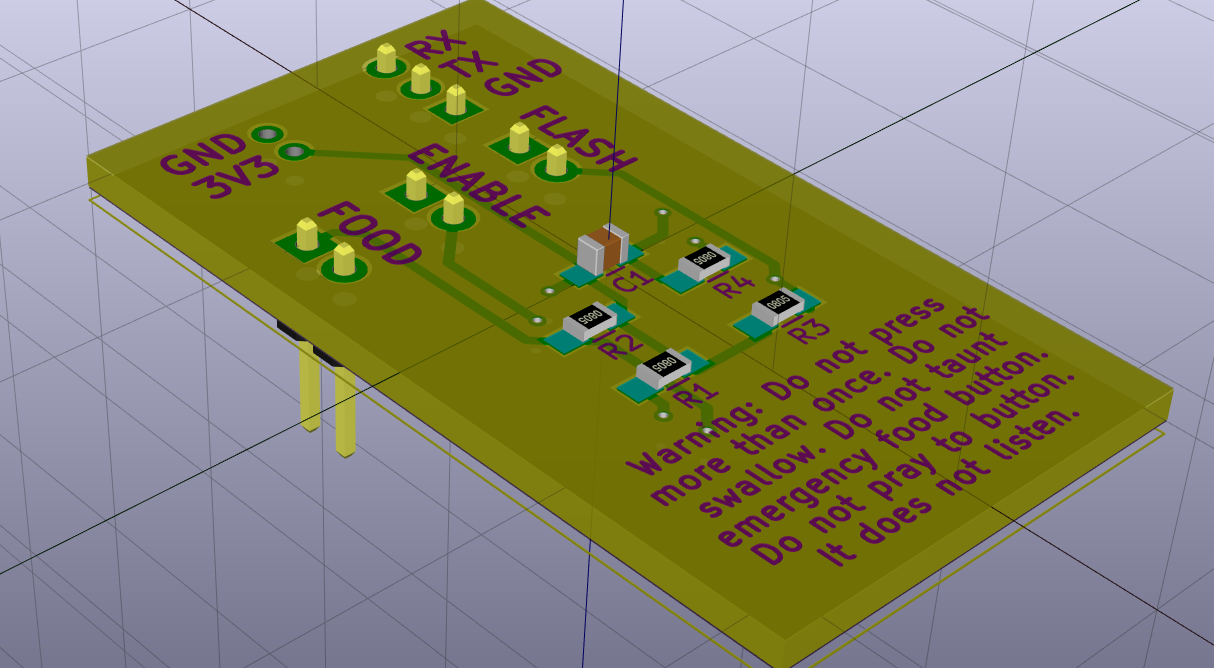
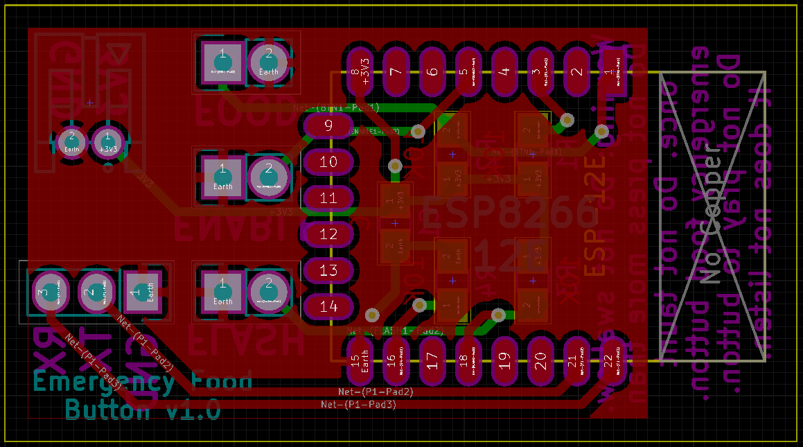 The complete, routed PCB.
You can see my finished PCB on the right (you can also order it from DirtyPCBs. Along with the tracks, you can add various bits of text on either side, either to mark which things are what (which you’ll want to do, trying to figure out two weeks later which headers are connected where isn’t great), or just for fun.
Another thing you need to be aware of is how much current you want to push over your traces. The ESP8266 is pretty power-hungry, so making your VCC traces too thin will lead to bad things happening. I’m not sure exactly what bad things, but I imagine your ESP will reboot or your traces will melt and your house will catch on fire or whatever.
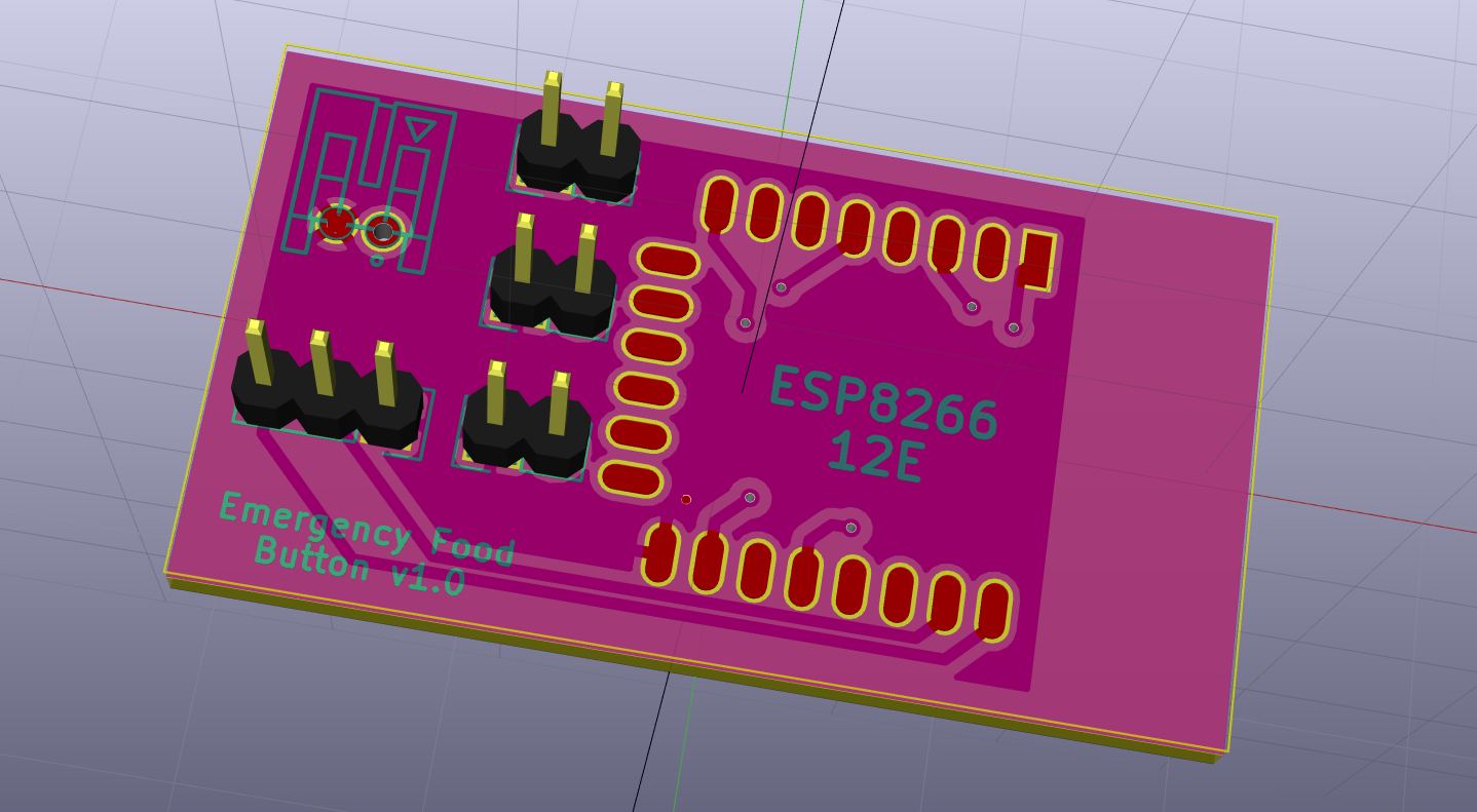 The top of the finished product.
In general, as long as your schematic is logically correct and works on the breadboard, KiCad will ensure that you won’t make any stupid mistakes. Its DRC checker will warn you if you leave things unconnected, or if traces are too close to each other, or if you shorted something, or committed any of a bunch of errors.
Of course, it can’t know about things like how much current you intend to push over a trace, or what the parameters of your fab are, so you need to make sure you’ve told it what your fab can support. Other than that, it seems like a pretty fool-proof process, and I’m hoping I won’t need to come back and edit this post on this point when I receive my PCBs.
 The bottom of the finished product.
Besides, for $14 per 10 PCBs, you can probably afford to make a few mistakes. The biggest problem is the large turnaround time (could be as long as two months), but luckily designing hardware turned out to be a cheapish and fun hobby.
Usage
After having all the fun designing and manufacturing the EFB, it will be used. All the components will go into the casing, and I’ll mount it on the wall. As you saw in the video, whenever I need some food, I’ll press the button, and I will very soon receive delicious Greek food, right on my doorstep.
I admit that it’s kind of a novelty at this stage, but I order out a lot, and it would be nice to not have to log on to the website, select an address, select a dish (I usually order the same), go to the payment page, confirm, wait for confirmation, etc. Having a button on the wall that I can press to get food is a great convenience, so maybe it won’t be as frivolous as I think it will be.
Epilogue
Three days ago, designing a PCB looked to me like a daunting affair, full of pitfalls that would make my design not work. That not only turned out to be false, given the large safety net that KiCad affords, but hardware design turned out to be great fun. I already have some more ideas for PCBs I want to design, and I don’t think I’m going to bother with that perforated board thingy I bought to permanently put my board on, given that I enjoy making PCBs so much.
I actually had to go through five iterations of the EFB PCB before actually shipping one off to production. The first one took a few hours, but after the second one I just scrapped the design if I saw that I needed to add a new component or do something that would require more than a slight change in the design. That goes to show how easy for me it is to route a simple PCB like the one above now, and, if you have even a passing interest in hardware, I would very strongly recommend that you download KiCad and give it a shot. The Udemy course in KiCad design helped me get started within an hour or two, and I can recommend it.
If you have any thoughts or feedback, please leave a comment below or get me on Twitter! I’d be happy to see what you’ve come up with.
UPDATE: Success!
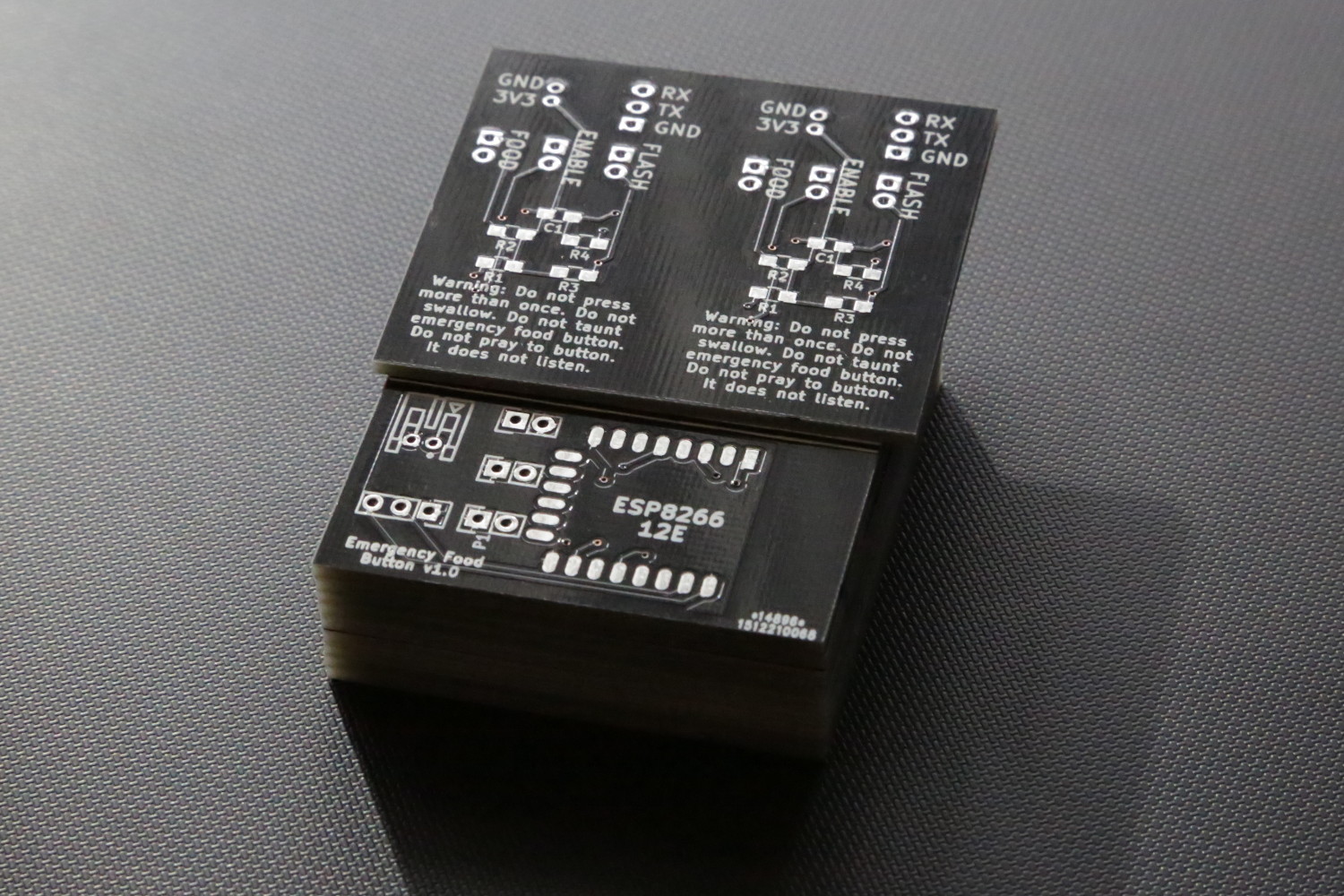 The actual thing! It looks so pretty :')
The PCBs have arrived! Holding the physical product of your labor in your hand is a fantastic feeling that you don’t get with software. All the more so when it’s the first PCB you’ve ever designed, and you solder everything up and it works! It feels fantastic, I urge you to design one if you have even a passing interest in hardware. The whole process was very enjoyable and pretty easy (shoutouts to the people in the ESP8266 Arduino channel and the Freenode #kicad channel for their invaluable assistance in making this).
I’ve connected everything up and it works beautifully, and fits very well in the enclosure. Here’s what the final assembly looks like:
I hope you enjoyed reading about this project at least a bit as much as I enjoyed making it, because I enjoyed the shit out of making it.
I’m joking, I’m sure that at least one person has designed and manufactured a PCB before.↩