If you have been following my erudite writings, you will know that I find great pleasure in taking things that don’t have computers in them and putting computers in them. I put a computer in a doorbell so I can order food, in a LED strip so I can play games better, an RC car so I can map out my living room, a room fragrance sprayer so… I can spray my room with fragrance, etc.
You will, of course, remember the iRotary, an old rotary phone that I turned into an amazing rotary mobile phone. You don’t? Well here it is:
You will also remember the irrigation controller that has the potential to revolutionize agriculture more than the Mesopotamian dude who said “I wonder what will happen if I put a bunch of seeds into the ground” 20,000 years ago but then was too lazy to do it. It probably won’t revolutionize it as much as his brother, who actually did it, but I’ll take what I can get.
Anyway, the problem with those two projects is that they use an Arduino, which is ancient 2014 technology, so they might as well be using a piece of flint on a stick. The iRotary prototype, more specifically, is a bunch of wires that I literally duct-taped on the Arduino because I figured I might want to use the GSM shield again (possibly to make an irrigation controller), so I’ve always wanted to improve on the two.
The obvious improvement would be to design a custom, extensible GSM PCB that I can program and easily solder to other things to make GSM-enabled devices, but who has the will, knowledge or time to do something huge like this? Well, I do, damnit, because I went and learned all these things while somehow managing to trick my girlfriend into believing that yes, I am spending enough time with her.
After the long and excessively meandering introduction, I am ready to take you through the detailed journey of how I made just that: A custom-built, programmable, GSM-enabled PCB, wrote the software for it and now make it available to you for free so you can make your own crap.
Let’s start!
The requirements
The two immediate requirements are:
- The board must be programmable.
- The board must have a GSM modem.
- The board must be magnificent.
For #1, I’m going to use an ESP8266, which is amazing and I love it and it’s great, so that’s what I’m going to use. As for #3, I’m taking it as a given that it’s going to be magnificent, as I strive for magnification in all my work. #2 is going to take a bit more figuring out.
The GSM modem
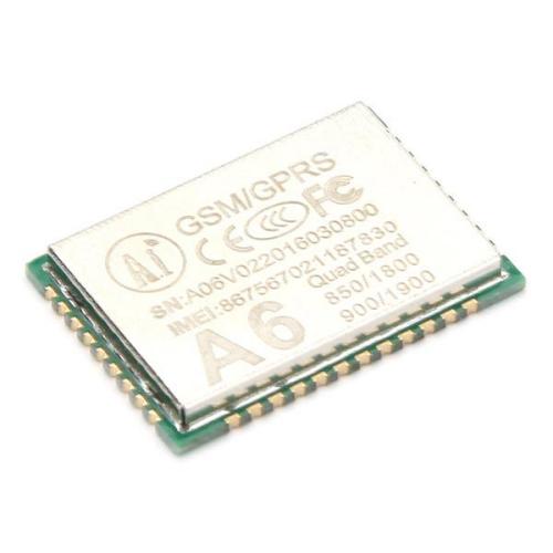 The A6 chip. It's smaller than it seems.
The GSM modem requirement is a big one. There aren’t that many GSM modems that are easy to work with on the hardware level, have working libraries and are reliable. I found two alternatives, the SIM900 and A6. The SIM900 has a working library, which I’ve used both for the iRotary and the irrigation controller, and it works well enough. The A6 is very cheap (~$2 per chip, if I remember correctly), but I didn’t manage to find a working library for it, which is a big minus.
However, the advantage of the A6 is that the hardware layout is much simpler, as it only requires a few resistors and capacitors. Since I’m a software developer, it’s much easier for me to hack a library together than to make a complicated board, especially since any mistake I make on the board will be much harder to debug, and will take a month to fix for each iteration. That distinction decided the outcome, and I went ahead and wrote a driver/library for the A6 modem.
Writing the library
Let me tell you, writing a library sucks, especially when you don’t know C, and doubly so when it’s for the A6. I spent a good few days writing it, about half of which were spent on figuring out how to get C to do things like return multiple values, and half spent figuring out why the A6 won’t do what I want it to.
The documentation for the A6 consists of a badly-translated AT command set and two PDFs of schematics for a breakout and a developer board. That is literally all that’s available, and emailing AI-Thinker with questions will get you a zip file of said PDFs, although they will be responsive and try to answer.
I spent countless hours trying to get the A6 to even initialize on time and start making sense, and fortunately I managed to get my library to deal with that reliably. The A6 might still just completely fail to initialize sometimes, in which case you have to reboot it, but at least I know what’s going on. I also still haven’t managed to get audio working properly, but I think the next version will fix that.
A few of the problem one has to face are:
- The A6 takes a variable amount of time to boot up. You pretty much have to loop over and over and go “Are you ready yet? How about now? How about now? How about now?”. That took me a few days to figure out.
- Figuring out how to send SMS was a bit hard, as the docs weren’t very clear.
- My A6 wouldn’t receive SMS at all unless the charset was UCS2. Guess how long it took me to randomly stumble upon that realization. Go on, guess. Nope, it was longer than that.
- The command to switch between speaker and headphones is in Chinese, and hasn’t been translated at all, so ctrl+F won’t find it. A few hours lost there.
- The sound quality in the breakout board I got on eBay is horrible. Hopefully the finished product will sound fine.
- I didn’t even go near a data connection. I’m waiting for someone better than me to write that.
- GSM is going to be sunset in the US soon, so if you’re from there, you probably won’t find this modem very useful, because it won’t work at all in a month or two. Hopefully this won’t happen in Greece, or I’ll choke someone.
Luckily, I’ve gone through all this trouble for you, so you can just install and use the library in a few lines, and avoid all the hassle. It supports making and receiving phonecalls, and reading and sending SMS, which is pretty much everything except for data connections. The chip does support them, but it would probably have taken me a year to implement.
You can find the source on my Github page:
https://github.com/skorokithakis/A6lib
It is also available in PlatformIO, so you can install it from there, if you use it. If not, start using it, it’s great.
Designing the board
After the hardware components have been decided, it’s time to design how to connect them together. I want the board to be as generic as possible, since I’m going to be using it to create all sorts of things, and since it needs to at least be able to be used in the iRotary and irrigation controller. That means that all the pins that are exposed by both the ESP8266 and the A6 need to be exposed in the final PCB itself.
The documentation on the A6 is pretty bad on the hardware side as well, so I have no idea what pins like the MIC+/MIC- ones do. Luckily, one of the boards has what appears to be a working mic jack, so I pretty much just copied what the board did and hope it works. It also appears to have a bunch of filtering capacitors and inductors, so I stuck those on the board as well, and I’m keeping my fingers crossed. This is how a surprising amount of product design gets done, so if you think it’s unusual, you won’t like how your car gets made.
Since the iRotary has connections for the speaker and microphone, it’s essential that these work well. The irrigation controller, in turn, needs all the ESP8266 pins, as it needs to be connected to various inputs and outputs. I generally like making my boards as small as possible, and not wasting space, so this one is going to be a bit tight, but I use both the front and back, so there’s plenty of space for laying out components in 50 square centimeters.
The size of the board is a very significant advantage, especially for the iRotary, because the prototype contains a full Arduino Uno with a GSM shield on top of it, which easily doubles its height and general bulk, and very nearly did not fit in the spacious phone enclosure. Due to that fact, I had to remove the phone’s ringer and replace it with a speaker, which is much less awesome.
This board, however, takes up around ten times less volume, so it’s much easier to work with. It also has through-holes, making it very simple to solder components on. Given that making a second iRotary with the same components as the first is almost impossible, the new board should allow me to make more, and even sell a few (if you want to buy a hand-assembled, fully working iRotary for $150ish, let me know).
The schematic
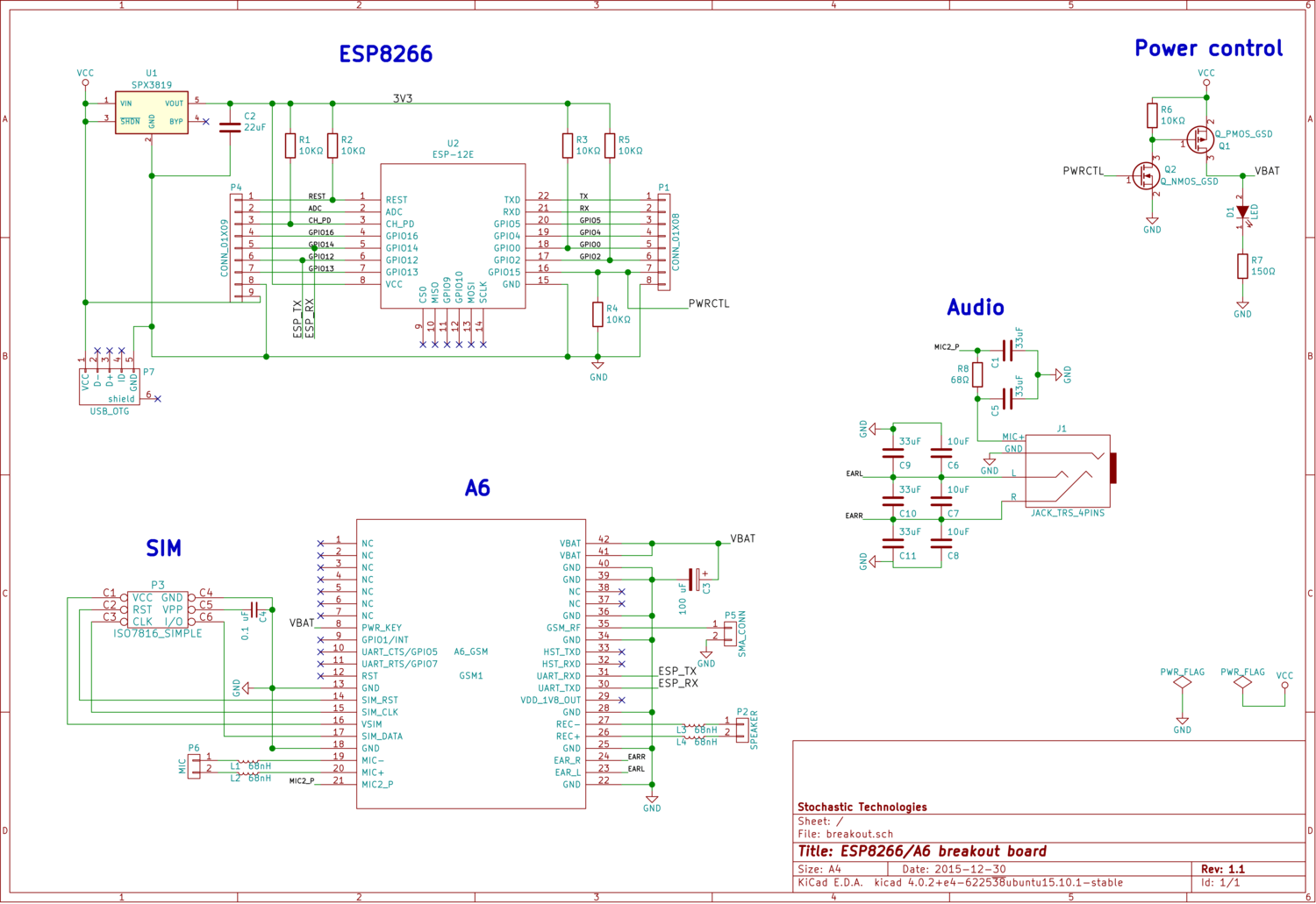 The schematic diagram of the board.
As always, I start with the schematic diagram. As you can see on the image, it consists of an ESP8266 with all its boot resistors/capacitors, an A6 and its capacitors, the audio filtering that was on the original board, and a simple power control system I designed.
The A6 has a “boot” pin that you can pull high to start the boot sequence, but I don’t see why I would want the modem to be powered on but not booting. I think it also has a reset pin, but I found it much easier to just completely cut turn its power on and off whenever I needed it, so I added an NMOS/PMOS pair to control the Vcc rail from the ESP. Simply output high to power the A6 on, and low to power it off.
An alternative was an N-MOSFET on the ground rail of the A6, but it didn’t seem safe to me to mess with the ground connection, especially when the antenna needs connects to ground as well. I added an indicator LED to the mix, so I can see when the modem is powered on or off, and the whole thing is working beautifully.
The PCB
Routing the PCB is, by far, the part I enjoy the most about the whole process. KiCAD pretty much ensures that you won’t make mistakes, you just need to account for amperage so you know how wide you want to make your tracks, and that’s about it, you’re then free to MSPaint the whole thing away.
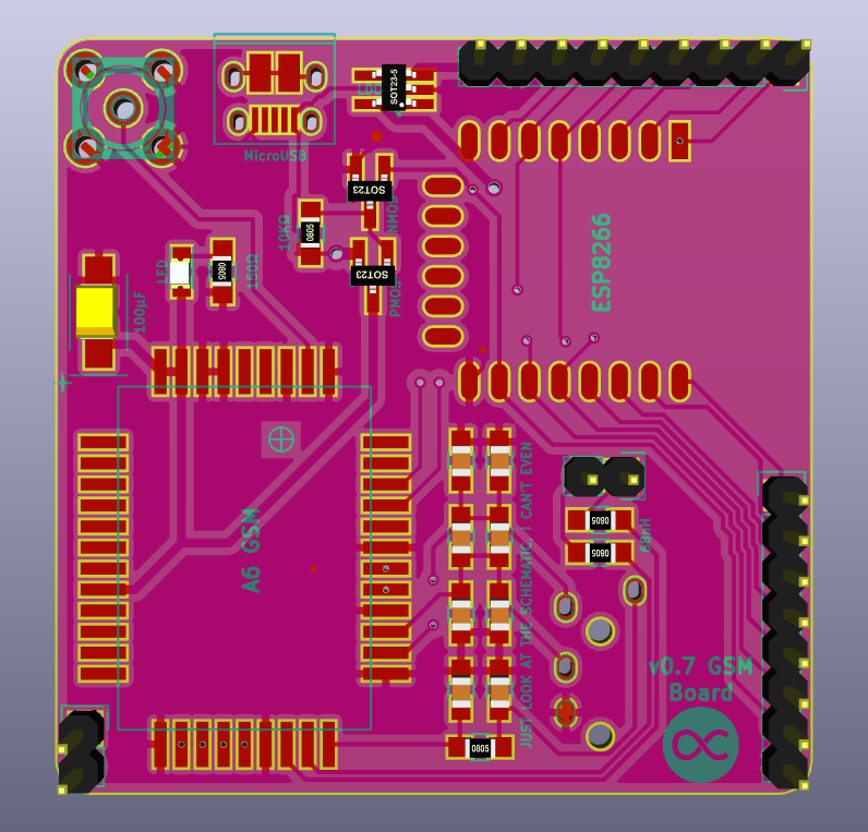 A 3D render of the board.
As you may have noticed from the adjacent 3D rendering of the PCB, I decided to add a MicroUSB socket so I can power the board from a USB cable. This is just for convenience, really, since MicroUSB is so ubiquitous. This way I can use an external battery or power bank, or a phone charger, or anything that puts out 5V to power the circuit.
Since the iRotary runs on a 3.7V-4V battery, and the A6 has a pretty wide range of voltages it will accept, I connected it directly to the USB power rail, and also to the VCC pin. The ESP8266 runs on 3.3V, so I added an LDO to convert Vcc to 3.3V. “LDO” stands for “low-dropout regulator”, which is just a confusing way of saying “voltage converter”, it converts a high voltage to a lower voltage suitable for low-power devices. Since I have an LDO, I need at least around 3.5V, which should be plenty when running off a 3.7V battery, and is definitely plenty when running off USB. Power draw seems to be around 0.2A at 5V on idle (i.e. not making a phone call) for the whole board, but I’ll make more accurate measurements later on.
The routed board looks pretty straightforward, the top has most of the components and the bottom has the SIM card holder and a few resistors and capacitors. I also added a headphone/mic jack, because I’m not courageous enough, but, as I mentioned, sound quality is not great. Hopefully the capacitors, resistors and inductors will fix this.
After spending some time routing the PCB, I decided I’d order one with whatever I had at the time, because I figured $14 isn’t that much to pay for a preliminary run. An added benefit is that I would discover any bugs earlier, and fix them for the final run. With that in mind, I went to DirtyPCBs and uploaded my designs, placed the order, then spent the next three hours frantically checking, double-checking, routing, rerouting and changing and fixing things, greatly improving the design.
Unfortunately, I added the audio filtering components right as the board was sent to the board house, so they aren’t on the first version. No matter, though, what was done was done and all that was left was to play the waiting game! If you’re not familiar, the waiting game is a very fun board game where players are waiters and you’re trying to win by scoring the highest tip by the time the restaurant closes. Anyway, the printed board was on its way!
The finished board
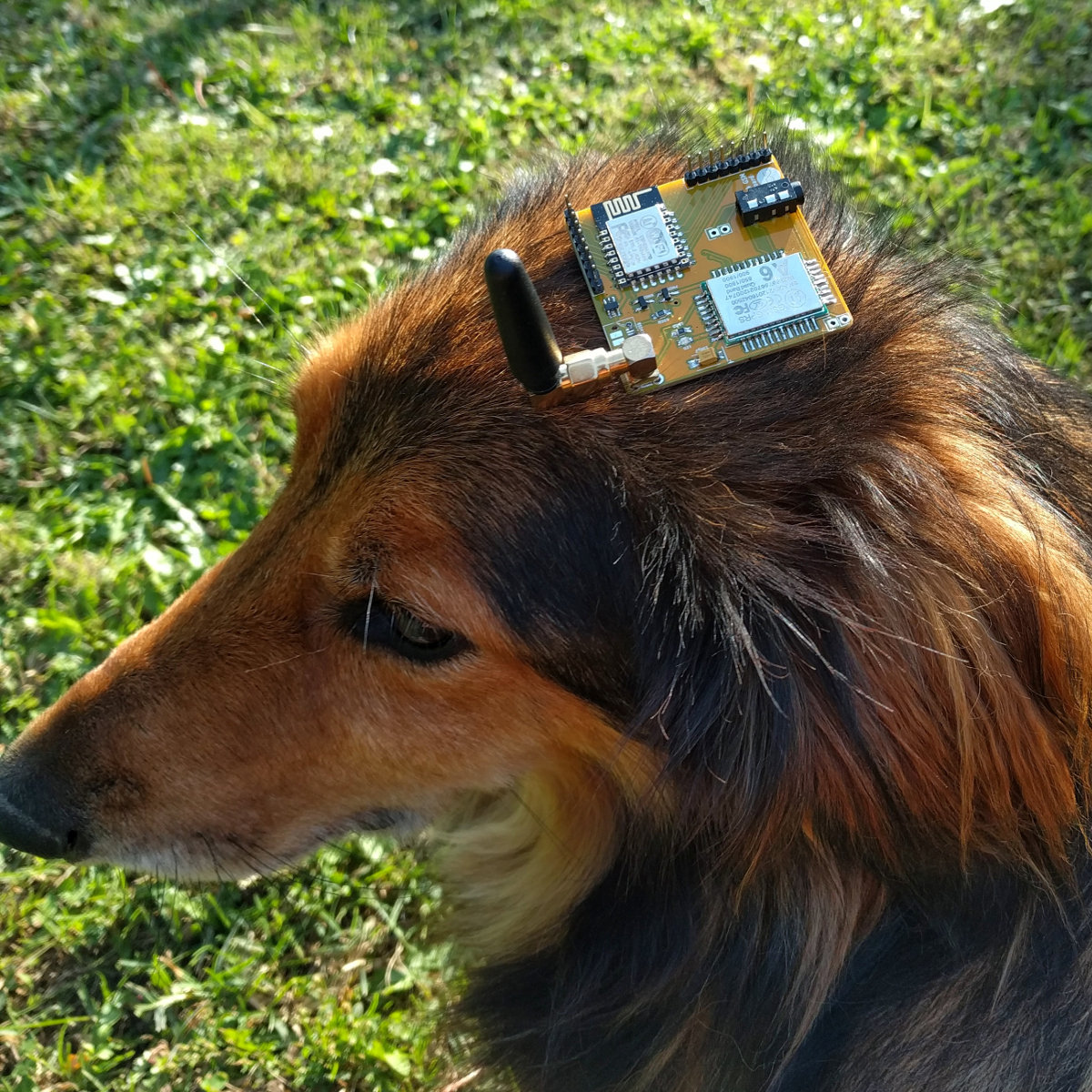 The physical board, with dog model for scale.
In a few short weeks, the printed board arrived (you can see it in the photo on the right, stapled to my dog’s head for ease of presentation). After getting the package, I soldered the components on one of the boards to try it out, using my new flux pen so stuff would be somehow easier to solder (at least that’s what the YouTube videos promised). Instead, the solder gooped and became gummy, making the soldering process take the better part of an hour.
After soldering, I plugged the board in to my FTDI programmer, but I had problems with the connection constantly dropping, blowing my USB fuses, and things like that. I connected it to the ammeter to measure current draw, which spiked to 3A right away and gave the room an earthy, metallic smell. It seems that I either short-circuited something, or took too long soldering and burnt the A6, because the board was toast.
I soldered a new one, forgoing the flux pen this time, and it worked beautifully. The headphone jack audio was, indeed, noisy and loud, so I will have to try the next batch, but the separate speaker and microphone connectors seem to be working well, which is promising for the iRotary. I did make one mistake, due to using the wrong component, and connected the wrong MicroUSB pin to ground, but that should be easy to fix while soldering (and I already fixed the problem on the KiCAD files).
Since this initial board version is missing the filters, I am going to use it mainly for the irrigation controller. I’m currently in the development stage, just porting the old code to use the A6lib library I wrote, and it should be ready soon. Everything has been working well during testing, except for the fact that signal reception isn’t great, but it’s not horrible either, so that’s not a big issue.
All in all, I am very pleased even with this early board version. It’s been rather reliable, and I don’t have any of the serial noise problems I was having with the development board, where the connection would reset when making or receiving a call, due most likely due to noise from the RF antenna in the data connection.
Epilogue
Having tested and programmed the board for around a week now, I’m very satisfied with it. It has been working pretty well while developing and using A6lib, and I hope it will continue working well as an irrigation controller in the field (literally). I wish I had submitted it in time to get the filtering components in, but I can always order a second batch, so I’m not too fussed.
If you want to order a printed board, or issue a pull request, or anything else, I have made the KiCAD files available on my Gitlab account:
https://gitlab.com/stavros/A6-ESP8266-breakout/
I don’t have a DirtyPCBs link for you, because I haven’t ordered the latest version yet, but exporting the Gerbers from KiCAD and ordering should work perfectly.
Also, here’s the code of the irrigation controller, in case you want to use the board with it:
https://gitlab.com/stavros/irrigation-controller/
If you do any work with the A6, and see something that A6lib doesn’t have, please issue a pull request. I’d especially appreciate cleaning up my crappy code to be more idiomatic C, or optimizing things I am doing suboptimally right now.
For any feedback, ideas or hate mail, you can leave a comment below or tweet to me. I’m especially interested in hearing from you if you use A6lib or the board in any of your projects.
Kisses!