After designing my first PCB, I went on a designing spree. It turns out that making PCBs (printed circuit boards, basically a piece of plastic that includes all the connections of your components in it. It helps make your project smaller and cut down on the amount of wires floating around) is so enjoyable, I’m PCBing all the things! The next victim for PCBfication is a circuit I had originally built on an Arduino and subsequently migrated to an ESP8266.
The circuit is a home sensor and controller. It can sense light, temperature, humidity and motion, and includes an RF controller (at 433 MHz) and an infrared LED so you can control your TV and other home devices. In this post, I’ll go into some detail about the build and how it connects to other sensors and controllers around the house.
This post is also a test of my new Expounder concept library. Throughout the post, various terms will be underlined like this (with a dashed underline), and you can click on them if you’re unfamiliar with the underlined term. After clicking, some text will expand and explain the term.
Let’s continue to details about the components!
The components
Since this is a home sensor circuit, I wanted the sensors to be relevant to a home scenario, and easy to get on eBay. The ones that fit that bill were a temperature and humidity sensor (DHT22, about $3), a pyroelectric motion sensor (about $1), and a photoresistor (a device that can sense the amount of ambient light, about $0.03).
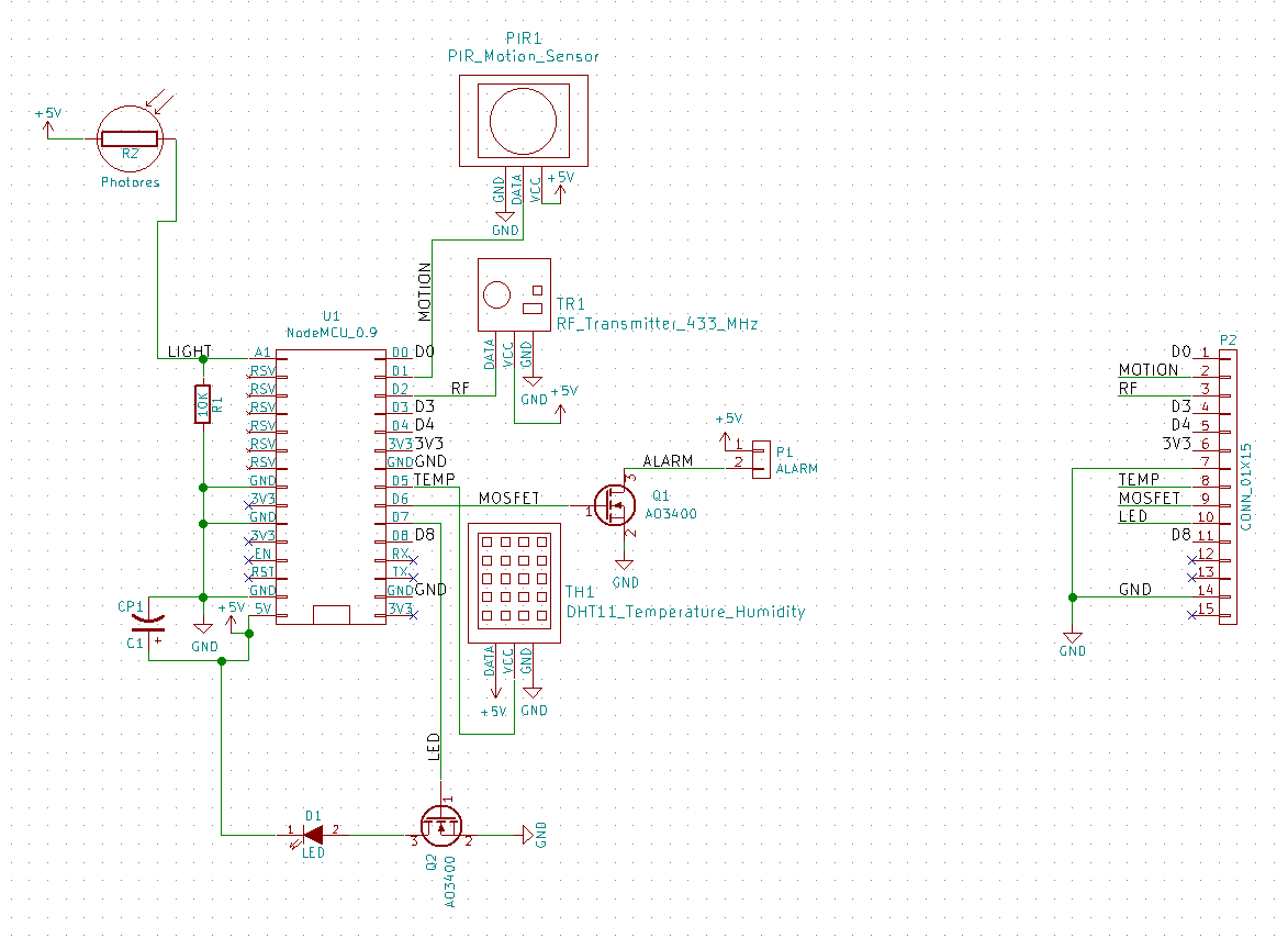 The circuit diagram.
Along with the inputs, it’d be nice if we could add some outputs. Ever since I made my first RF socket controller, I’ve found it very useful to be able to turn lamps on and off depending on the ambient light in each room, and whether there’s someone in the room. So, it would be great if the board could include an RF transmitter, which will control the plugs in each room. Since I’m adding support for the sockets, I might as well also add IR support, so I can control my TV, air conditioning unit, etc. I also got one of those window alarm units and gutted it, so I can add a spot for that as well. That way, I can make noise at will and annoy the neighbours!
Wiring everything together is pretty simple, so the first step is to draw up the wiring diagram in my trusty and beloved KiCad. You can see the final design on the right, it’s pretty simple and based on a NodeMCU. The NodeMCU is a breakout board based on the ESP8266. It basically provides all the components the ESP8266 needs to boot and operate stably, in one friendly package. You may be aware that there are multiple NodeMCU designs floating around, and the first iteration of the board (photos of which you’ll see in this post) were based on an early version, which was a mistake. This time I’ve learnt my lesson, and v1.1 will be compatible with both popular NodeMCU versions, as you will see.
The PCB
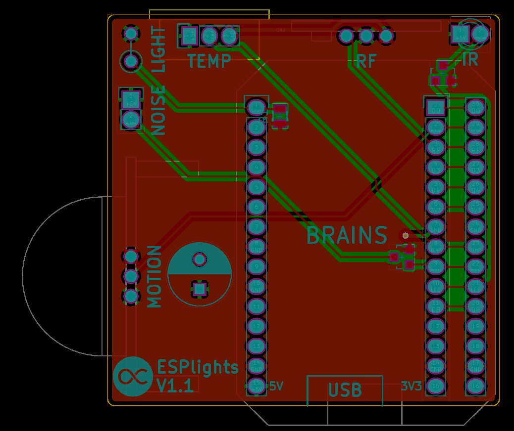 This is what the diagram of the PCB looks like.
Designing a PCB is the fun part. However, some sensors are pretty non-standard, and coming up with the right wiring can be tricky. For that reason, I had to design my own footprints and schematics, which was pretty easy (especially with my trusty caliper to help), but you need to watch out for mistakes in the order of the pins.
I also want to be able to reuse sensors, so I don’t want to solder anything that costs over a dollar to the PCB, which means that I’ll have to use female headers for this build. The headers are basically little plastic bits that I will solder on the PCB instead of the sensor itself, which will allow me to just plug the sensors in and out, as I need them. Since I also want to support multiple NodeMCU versions, I’ll be using two rows of headers for one leg of the MCU, with each pin connected to the next one, so I can plug either the narrow or the wide NodeMCU in and have it work. The pin order is the same in both cases, so I’ll just need to connect adjacent pins together.
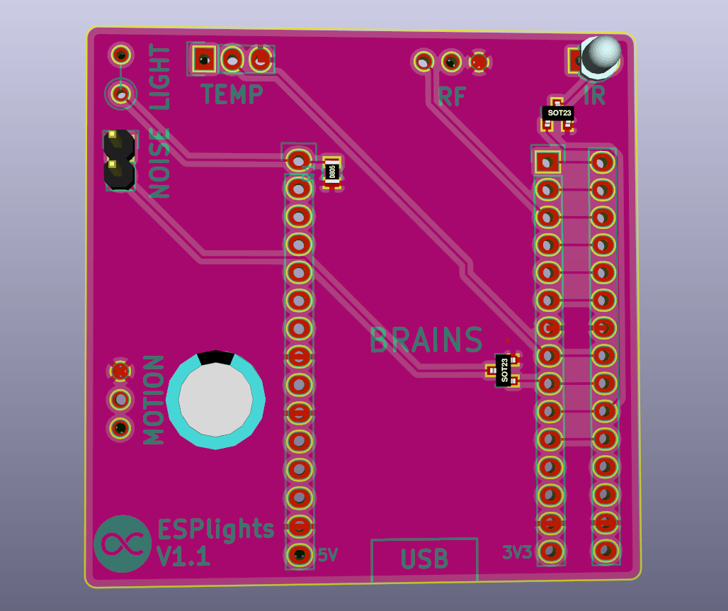 A 3D model of the PCB diagram.
The diagram of the PCB, as it will look when fabricated, is shown on the right. The two NodeMCU widths are on the bottom right, and the sensors are labeled, starting from the bottom left and continuing clockwise to the top right. The light sensor is going to be soldered to the board directly, which is why its pins are farther apart, but the rest of the components will all be connected by female headers. Still, the dimensions and distances need to be measured so the components can fit comfortably next to each other.
The large capacitor at the bottom right is also rather optional, but some people suggested it and there was room on the PCB, so I added one just to be on the safe side. The capacitor is useful for regulating voltage so the ESP8266 is protected against voltage spikes or drops (pretty much like a shock absorber for your battery). Hopefully, the USB charger/port will produce pretty even output, but I figured the capacitor can’t hurt, so I added the holes, plus I can always just not solder one.
The software
All these sensors need to be hooked up to some fancy software I wrote. It has many independent parts, which I will go into more detail here.
Communication
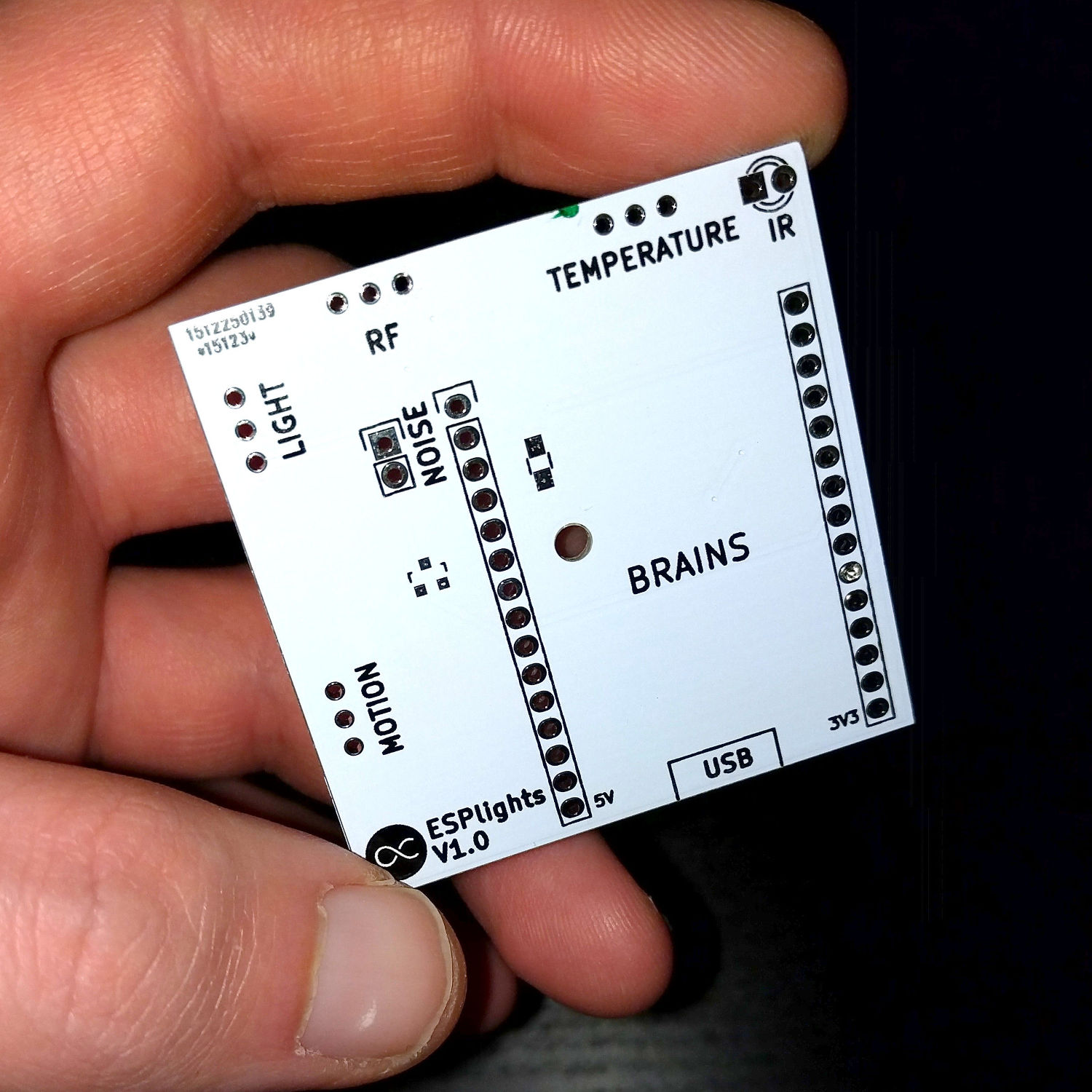 The physical PCB of the first iteration.
Since we have a bunch of components we want to read and control, we need to communicate with the board somehow. The easiest way to do this is with MQTT, which I quite like. In short, MQTT allows your devices to all connect to a server and join channels (called topics), where they can post information to each other. The board will post information about all the sensor readings and various parameters and configuration to a channel every second, where other scripts can connect to and read it. I chose JSON for the information, since it was easy enough to do and everything can read JSON.
To transmit commands to the controls, we send the commands to a different channel using a small Python script I wrote, and the board receives them and acts on them. Some commands (like the alarm) are simple, and some (like the infrared LED) are more complicated. Let’s see how those work.
Sending signals
The signals to send are rather varied, so I needed a method that can accommodate all the potential encodings. Since both RF and IR will use the same code, it had to work for both. Both use a carrier frequency, but we only need to modulate that in the case of IR, as the RF module handles modulation itself when transmitting.
To represent the codes themselves, I send the sequence of highs and lows as
integers representing microseconds. For example, if I send 1000 500, the MCU
will transmit HIGH for 1000 μsec and LOW for 500 μsec. Combined with the large
RAM in the ESP8266 (40 whole kilobytes!), I can send rather large signals even
where the Arduino I was previously using would just choke.
For the carrier frequency modulation, I pass two parameters, again integers. Those represent the number of microseconds to pulse HIGH and LOW. For example, if I’m sending a 1000 μsec pulse, as above, with a duty cycle of 20/10, this HIGH will actually get represented as 20 μsec HIGH, 10 μsec LOW, 20 μsec HIGH, etc, until 1000 μsec pass. LOWs are just sent as a continuous LOW.
This way, I can send any signal with any duration and carrier, down to a carrier duty cycle of 1 μsec. I quite like how accurate the ESP8266 is in this regard, although I’ve had some issues with things not sending, or not responding. The issues went away with leaving the whole thing off for a while, so I’m not quite sure what caused them in the first place. In any case, the system works very well for my purposes.
Automation
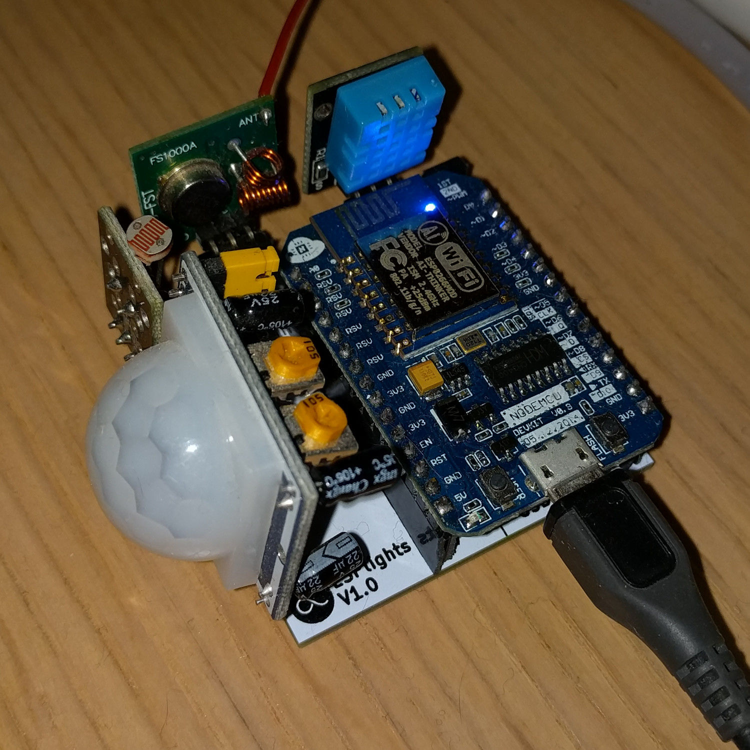 The PCB with all the sensors connected.
Since the whole purpose of this board is to be able to control lights in my house when I enter or leave, I wrote some automation to do just that. The rules are pretty much the following three:
- A light should be turned on if ambient light is low and there has been motion in the last ten minutes.
- The light should be turned off if there hasn’t been motion in the last ten minutes.
- The light should be turned off if there’s a rise in ambient lighting (for when I turn another light on).
This is achieved by a simple if-check with appropriate values for light and motion. One thing to watch out for was that the board should remember the light state and only turn it on if it’s already off, and vice-versa. This has the pleasant side-effect of allowing me to turn the light on or off if the board thinks it’s controlling it, which lets me turn it off even though I’m in a dark room otherwise, or turn it on even though there is enough ambient light already.
Control
To use the board’s controller functionality, I wrote an Android app a while back. This app is, unfortunately, HTTP-only, so I have a gweet server listen to messages from the app, and a Python script continuously look at the messages and relay them to MQTT. This setup is a bit overcomplicated, but it allows me to do nice things like TLS with HTTP Basic authentication (basically, it allows me to easily set a username and password so random people from the internet don’t have access to control my house).
I created a basic panel of buttons for Tungsten, so I can have panels for the TV, AC, lights, etc in my house. I also use Tungsten for controlling the custom WiFi-enabled LED strip controllers I made, which allows me to change the light intensity and color for any room in the house wirelessly, but that’s another post.
The code
As always, I’m making all the sources and KiCad files available on the project’s GitHub page:
https://github.com/skorokithakis/esplights
I may not be running this exact version at home, just to protect my private passwords and things, but I’ll try to keep this reasonably updated. Pull requests and bug reports are very welcome, as my C is very, very weak.
Epilogue
I know that this post isn’t as interesting as some of my other ones, but that’s mainly because this board is pretty ad-hoc and really only meant to work for me. Even so, I hope that you’ve gotten some inspiration for making your own projects, or some information about how to do one of the many things this does. In my opinion, the code and associated python script for sending signals are particularly interesting and can be reused for your own projects. I hope at least some portion of the code has been useful to you.
For any feedback, send me a tweet or leave a comment below, I am sincerely interested in hearing what you’re making, and chatting with you about it.